background image

308660

3

Pressure Control

WARNING

INJECTION HAZARD

To reduce the risk of serious injury,
whenever you are instructed to relieve
pressure, follow the 

Pressure Relief

Procedure

 on page 8.

NOTE: 

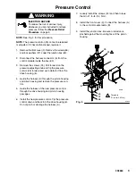
See Fig. 3 for this procedure.

NOTE: 

The pressure control (25) cannot be repaired

or adjusted. If it has malfunctioned, replace it.

1.

Remove the front cover (9). Remove the screws (65)
and lock washers (37). Lower the junction box (63).

2.

Disconnect the harness connector (A) from the
control module inside the box (63).

3.

Remove the screws (24). Pull forward on the
pressure adjusting knob and tip the pressure
control (25) forward and up to detach it from the
drive housing (6).

4.

Guide the harness (A) through the pinion housing
and drive housing and remove the pressure con-
trol.

5.

Guide the harness of the new pressure control
through the drive housing and pinion housing
passages.

6.

Install the new pressure control. Tip the pressure
control down and back into the drive housing (6).
Do not pinch or damage the harness (A).

7.

Loosely install the screws (24) and then torque
them to 21 in–lb (2.4 N.m).

8.

Install the front cover (9). Connect the harness (A)
to the control module leads (B).

9.

Install the junction box. Be sure no leads are
pinched against the mounting face of the pinion
housing.

06012

05834

25

24

63
37

A

9

6

Torque to
21 in–lb (2.4 N.m)

Fig. 3

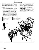
1

1

65

B

Summary of Contents for GM 3000

Page 1: ...all it may stay at tached to the drive housing or to the pinion housing Do not lose the thrust balls 6a and 2d or let them fall between the gears which will damage the drive housing if not removed If the balls are not in place the bearings will wear prematurely 7 Remove and inspect the crankshaft 8 and the connecting rod 10 Installation 8 Lubricate the inside of the drive housing bronze bearing wi...

Page 2: ...que to 100 in lb 11 N m 3 2 Quantity of three Quantity of one Lubricate with SAE non detergent oil 4 16 15 10 9 25 6 16 5 8 3 65 6a 2d A 26 23 REF A 19 68 1 1 2 3 4 2 69 64 05833A 06003 Fig 2 Brush and recoat with bearing grease Pack with bearing grease 3 4 tube ...

Page 3: ... and tip the pressure control 25 forward and up to detach it from the drive housing 6 4 Guide the harness A through the pinion housing and drive housing and remove the pressure con trol 5 Guide the harness of the new pressure control through the drive housing and pinion housing passages 6 Install the new pressure control Tip the pressure control down and back into the drive housing 6 Do not pinch ...

Page 4: ...washers 16 4 Pull the pinion housing 2 away from the clutch housing 1 The armature 51b will come with it 5 Pull the armature 51b off the hub 2h of the pinion housing Also see Fig 5 6 If replacing the complete pinion housing assembly 2 brush bearing grease supplied on the pinion shaft teeth Then recoat the pinion shaft teeth with bearing grease supplied Pack the remaining bearing grease in the bott...

Page 5: ...ion housing 7 Go to Reassembly page 29 Step 7 or continue on page 24 If you purchased parts separately follow steps 1 to 9 below Disassemble only as far as needed for the parts being replaced NOTE The old bearing 2g will be damaged as it is removed Have one on hand if you need to remove it for any reason Always replace bearing 2g if installing a new hub 2h 1 To replace small bearing 2n or roller c...

Page 6: ... kit to the face of the armature Engage the tabs on the spacer with the slots in the arma ture or bend tabs over outside diameter of arma ture Brace the cart against a wall to keep it from rolling Push the drive pinion assembly onto the clutch housing 1 There will be significant resistance When the mating surfaces of the drive pinion as sembly and the clutch housing 1 are flush re move the drive p...

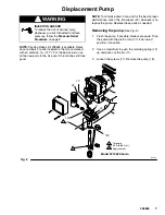
Page 7: ...he kit even if the old ones still look good NOTE To minimize down time and for the best sprayer performance clean the transducer 22 whenever you repack the pump Replace these parts as needed Removing the pump See Fig 8 1 Flush the pump if possible Relieve pressure Stop the pump with the piston rod 107 in its lowest position if possible 2 Use a screwdriver to push the retaining spring 12 up and pus...

Page 8: ...ly relieved to prevent the system from starting or spraying accidentally Fluid under high pressure can be injected through the skin and cause serious injury To reduce the risk of an injury from injection splashing fluid or moving parts follow the Pressure Relief Procedure whenever you D are instructed to relieve the pressure D stop spraying D check or service any of the system equipment D install ...

Reviews: