background image

Maintenance 

10

3A4100D

Maintenance

Packing Nut / Wet-Cup

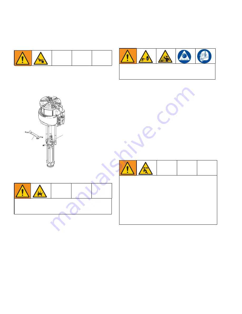
1. Fill the packing nut/wet cup (P) 1/3 full with Graco 

Throat Seal Liquid (TSL). 

2. Use the supplied wrench (Q) to adjust the packing 

nut weekly so that it is just snug. Do NOT 
over-tighten. 

Flushing the Pump

The pump is tested with lightweight oil, which is left in to 
protect the pump parts. If the fluid you are using may be 
contaminated by the oil, flush it out with a compatible 
flush material before using the pump. 

Flush at the lowest pressure possible. check 
connectors for leaks and tighten as necessary.

Flush with a fluid that is compatible with the fluid 
being dispensed and the equipment wetted 
parts.

1. Perform the 

Pressure Relief Procedure

 on page 9.

2. Set pump to lowest possible fluid pressure, and then 

start the pump.

3. Dispense fluid into a grounded metal pail. 

Disconnecting the Displacement 
Pump

1. Flush the pump if you are using flushable material. 

2. Stop the pump at the bottom of its stroke. 

3. Perform the 

Pressure Relief Procedure

 on page 9.

4. Disconnect the air or the hydraulic hose. Plug all 

hydraulic hoses immediately to prevent the contami-
nation of the hydraulic system. Hold the fluid outlet 
fitting with a wrench to keep it from being loosened 
while you disconnect the fluid hose. 

5. Disconnect the displacement pump (G) from the 

motor (F) as follows. Make sure to note the relative 
position of the pump fluid outlet to the air or hydrau-
lic inlet of the motor due to orientation restrictions on 
the system. If the motor does not require servicing, 
leave it attached to its mounting. 

6. Using adjustable wrenches to unscrew the coupling 

nut (J) from the coupling adapter (H). Remove the 
coupling collars (K). Take care not to lose or drop 
the collars. 

7. Hold the tie rod (L) flats with a wrench to keep the 

rods from turning. Unscrew the hex nuts (N) from 
the tie rods extensions. Carefully remove the dis-
placement pump (G) from the motor (F). 

To reduce the risk of serious injury, do not flush pump 
with group 1 fluids as defined by Directive 2014/68/EU 
(Pressure Equipment Directive).

WLD

4

3

To reduce the risk of serious injury whenever you are 
instructed to relieve pressure, always follow the 

Pres-

sure Relief Procedure

 on page 9.

Be sure to use at least two people when lifting, moving, 
or disconnecting the pump. This pump is too heavy for 
one person. If you are disconnecting the displacement 
pump from a motor which is still mounted (for example, 
on a wall bracket), be sure to support the displacement 
pump while it is being disconnected. Failure to do so 
may result in the pump falling and causing injury or 
property damage. Do this by securely bracing the 
pump, or by having at least two people hold the pump 
while another person disconnects it. 

Summary of Contents for Dura-Flo 25A451

Page 1: ...defined by Directive 2014 68 EU Pressure Equipment Directive Not approved for use in European explosive atmosphere location See Technical Specifications page on page 19 for maximum allowable ambient...

Page 2: ...mp Lower Ratio Maximum Fluid Working Pressure Maximum Air Input Pressure 25A451 Series A XL 1000cc Severe Duty Carbon Steel 25A455 XL 24000 25A447 Dura Flo 1800 1000cc 47 1 4500 psi 31 MPa 310 bar 100...

Page 3: ...g and before cleaning checking or servicing equipment Tighten all fluid connections before operating the equipment Check hoses and couplings daily Replace worn or damaged parts immediately FIRE AND EX...

Page 4: ...r pressure Turn off all equipment and follow the Pressure Relief Procedure when equipment is not in use Check equipment daily Repair or replace worn or damaged parts immediately with genuine man ufact...

Page 5: ...mbly Instructions 1 Assemble H to F Apply sealant and torque 2 Assemble L to F and torque 3 Assemble G to L and hand tighten N 4 Assemble K and torque J to H 5 Torque N to L Ref Description A Pump B S...

Page 6: ...Air Valve BB Air Inlet 1 in npt f CC Muffler DD Pilot Valve EE Manifold FF Manual Shuttle Override Button GG Ground Screw HH Static Ground Cable JJ Plug for Optional Solenoid KK Optional Reed Switch...

Page 7: ...h a maximum of 500 ft 150 m combined hose length to ensure grounding continuity Check electrical resistance of hoses If total resistance to ground exceeds 29 megohms replace the hose immediately Air c...

Page 8: ...6 as needed Assemble with pipe sealant 4 Install mounts 3 and gaskets 4 Torque to 15 18 ft lb 20 24 N m 5 Install air motor F onto the system See system manual for further instructions NOTE For Uni Dr...

Page 9: ...em Have a container ready to catch the drainage 4 Open the pump bleed valve S NOTE Have a con tainer ready 5 Leave the bleed valve open until you are ready to spray dispense again Follow the Pressure...

Page 10: ...hose 5 Disconnect the displacement pump G from the motor F as follows Make sure to note the relative position of the pump fluid outlet to the air or hydrau lic inlet of the motor due to orientation r...

Page 11: ...241648 249991 and 15F298 limit torque to 27 40 N m 20 30 ft lb Torque to 459 481 N m 338 354 ft lb Torque oppositely and evenly to 244 264 N m 180 195 ft lb Apply anti seize lubricant to threads and...

Page 12: ...SING intake 1 184275 184275 184390 184390 19 HOUSING outlet pump 1 184290 184290 184389 184389 20 BOLT 6 17L291 128710 17L291 17L291 21 PLATE designation 1 184446 184446 184446 184446 22 SCREW drive 4...

Page 13: ...Lower Parts 3A4100D 13 Air Motor 25A455 WL D...

Page 14: ...n with magnet 1 19 25A915 KIT bumper top and bottom with screws 1 21 108014 PACKING o ring 1 22 GASKET end cap 2 23 110036 BOLT M8 x 1 25 x 45 mm 4 24 17B389 SCREW M8 x 1 25 x 45 mm 4 25 127582 SCREW...

Page 15: ...A455 25A455 25A455 25A455 1 H ADAPTER rod 184582 184582 184582 184582 1 J COLLAR coupling 184130 184130 184130 184130 2 K NUT coupling 184096 184096 184096 184096 1 N NUT mach hex 106166 106166 106166...

Page 16: ...4 109312 V PACKING piston PTFE 5 Throat Packings Piston Packings TI8389a2 TI8389a1 25 36 29 26 11 35 33 34 TI8389a2 TI8389a1 25 26 29 11 34 33 Throat Packings Piston Packings 222849 Repair Kit for Dur...

Page 17: ...9 Ring retaining 11 Cover bottom 1 24X560 Muffler Repair Kit 15F674 Label warning 51 Foam Dampers 46 Cylinder Motor 3 24A915 Bumper Kit Bumper bottom 19 Bumper top 20 Screw top 3 29 Part Description A...

Page 18: ...outs WL D 63 6 1615 4 mm 20 8 528 3 mm 42 8 1087 1 mm 28 2 716 3 mm 19 9 505 5 mm 6 M16 x 2 0 Holes 8 0 in 203 mm 5 906 in 150 mm 6 186 in 157 22 mm 3 3 8 16 Mounting Studs 10 63 in 270 mm 4 3 8 16 Mo...

Page 19: ...Maximum Pump Operating Temperature 100 F 37 8 C Stroke Length 11 25 in 286 mm Air Motor Piston Effective Area 132 7 in 2 856 cm2 Displacement Pump Effective Area 2 79 in 2 18 cm2 Total Sounds Power 9...

Page 20: ...material or workmanship repairs will be made at a reasonable charge which charges may include the costs of parts labor and transportation THIS WARRANTY IS EXCLUSIVE AND IS IN LIEU OF ANY OTHER WARRAN...

Reviews: