Graco Dispensit 1053-10C Operation & Maintenance Manual Download Page 6

Important Isocyanate (ISO) Information


6

3A0874F

Important Isocyanate (ISO) Information

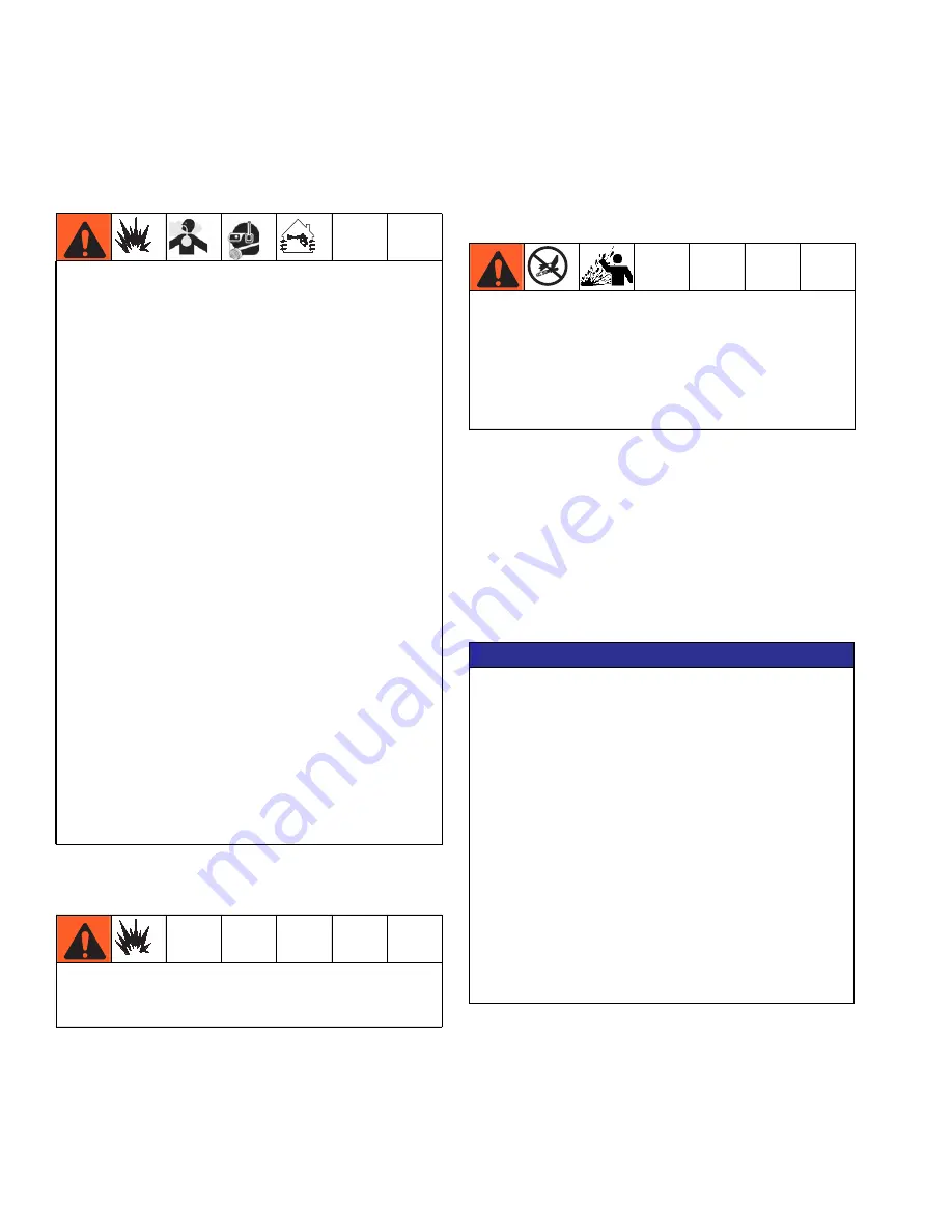
Isocyanate Conditions

Material Self-ignition


Keep Components A and B 
Separate

Moisture Sensitivity of 
Isocyanates

Exposure to moisture (such as humidity) will cause ISO 
to partially cure, forming small, hard, abrasive crystal 
that become suspended in the fluid. Eventually a film will
form on the surface and the ISO will begin to gel, 
increasing in viscosity.

NOTE:

 The amount of film formation and rate of crystal-

lization varies depending on the blend of ISO, the 
humidity, and the temperature.

Spraying or dispensing fluids that contain isocyanates
creates potentially harmful mists, vapors, and
atomized particulates.

Read and understand the fluid manufacturer’s 
warnings and Safety Data Sheet (SDS) to know 
specific hazards and precautions related to isocy-
anates.

Use of isocyanates involves potentially hazardous 
procedures. Do not spray with this equipment 
unless you are trained, qualified, and have read 
and understood the information in this manual and 
in the fluid manufacturer’s application instructions 
and SDS.

Use of incorrectly maintained or mis-adjusted 
equipment may result in improperly cured material. 
Equipment must be carefully maintained and 
adjusted according to instructions in the manual.

To prevent inhalation of isocyanate mists, vapors, 
and atomized particulates, everyone in the work 
area must wear appropriate respiratory protection. 
Always wear a properly fitting respirator, which 
may include a supplied-air respirator. Ventilate the 
work area according to instructions in the fluid 
manufacturer’s SDS.

Avoid all skin contact with isocyanates. Everyone 
in the work area must wear chemically imperme-
able gloves, protective clothing and foot coverings 
as recommended by the fluid manufacturer and 
local regulatory authority. Follow all fluid manufac-
turer recommendations, including those regarding 
handling of contaminated clothing. After spraying, 
wash hands and face before eating or drinking.

Some materials may become self-igniting if applied 
too thick. Read material manufacturer’s warnings and 
material Safety Data Sheet (SDS).

Cross-contamination can result in cured material in 
fluid lines which could cause serious injury or damage 
equipment. To prevent cross-contamination:

Never interchange component A and component 
B wetted parts.

Never use solvent on one side if it has been con-
taminated from the other side.

NOTICE

Partially cured ISO will reduce performance and the life 
of all wetted parts.

• Always use a sealed container with a desiccant 

dryer in the vent, or a nitrogen atmosphere. 

Never 

store ISO in an open container.

• Keep the ISO pump wet cup or reservoir (if 

installed) filled with appropriate lubricant. The 
lubricant creates a barrier between the ISO and 
the atmosphere.

• Use only moisture-proof hoses compatible with 

ISO.

• Never use reclaimed solvents, which may contain 

moisture. Always keep solvent containers closed 
when not in use.

• Always lubricate threaded parts with an 

appropriate lubricant when reassembling.

Summary of Contents for Dispensit 1053-10C

Page 1: ...1200 psi 8 MPa 83 bar Maximum Material Inlet Pressure Plastic Sleeves 400 psi 2 8 MPa 28 bar Maximum Material Inlet Pressure 100 psi 0 7 MPa 7 bar Maximum Air Working Pressure 110 F 43 C Maximum Ambie...

Page 2: ...Electrical Requirements 28 Technical Data 29 Motor Specifications 29 Graco Standard Warranty 30 Graco Information 30 Related Manuals Component manuals in U S English 1053 10C Valve Models Part Descri...

Page 3: ...h stroke 250 diameter rod stainless steel wetted components NEMA 23 motor ready A2A10309 1053 10C 4TT1 375 V NEMA23 2 INCH 2 inch stroke 375 diameter rod stainless steel wetted components NEMA 23 moto...

Page 4: ...y Replace worn or damaged parts immediately TOXIC FLUID OR FUMES HAZARD Toxic fluids or fumes can cause serious injury or death if splashed in the eyes or on skin inhaled or swallowed Read Safety Data...

Page 5: ...e compatible with equipment wetted parts See Technical Specifica tions in all equipment manuals Read fluid and solvent manufacturer s warnings For complete infor mation about your material request Saf...

Page 6: ...respiratory protection Always wear a properly fitting respirator which may include a supplied air respirator Ventilate the work area according to instructions in the fluid manufacturer s SDS Avoid all...

Page 7: ...s used in your equipment requires special attention to avoid equipment damage and downtime When changing materials flush the equipment multiple times to ensure it is thoroughly clean Always clean the...

Page 8: ...y meters liquid and semi paste materials The machine is designed for application that require very small and precisely dispensed beads and or dots of material at a wide range of material inlet pressur...

Page 9: ...Component Identification 3A0874F 9 Component Identification Typical System Configurations FIG 1 CONTROL POWER 9 40 0 8 46 0 5 0 4 Valve Controls System shown with optional controls...

Page 10: ...D WEARING SAFETY GLASSES WARNING F 20 0 psi 0 20 oz Cartridge Feed with Mounting Post 5 Gallon Pail Cover with Diaphragm Pump 1 Gallon Ram and Pump 5 Gallon Pail Cover with Diaphragm Pump and Agitator...

Page 11: ...tinued FIG 3 R 0 12 8 4 psi 30 22 19 15 26 R 0 12 8 4 psi 30 22 19 15 26 5 Gallon Tank with Diaphragm Pump and Stand 5 Gallon Tank with 5 1 Pump and Stand 10 Gallon Tank with Diaphragm Pump Agitator V...

Page 12: ...ng Rod E Oil Cup Retaining Block F Dispense Air Inlet G Reload Air Inlet H Lower Sensor I Upper Sensor J Drive Nut K Drive Screw L Drive Coupling M Sensor Amplifiers N Oil Cup O Wet Cups P Drive Locki...

Page 13: ...s 3 Connect each 1 4 in outside diameter supplied air line to the corresponding control solenoid See Component Identification starting on page 9 4 Connect chemical lines from feed system to meter ing...

Page 14: ...shown is for controls motor integrated For valve without controls motor integrated mounting pat tern is the same just less LS Home solenoid open close and all the wires terminated at a plug FIG 6 WL D...

Page 15: ...If using a non Graco motor with the dispense valve use the following diagram to install the non Graco motor onto the valve See Motor Specifications on page 29 2 22 2 22 2 039 0 182 2 039 0 182 0 251...

Page 16: ...ure 3 Dispense several full stroke shots until material is air free and has good shut off at the nose NOTE Very viscous compressible materials may con tinue to droll after system is primed Reduce flow...

Page 17: ...metering chambers by a pressurized feed system Outlet port is blocked Metering rod is retracted to a precise position deter mining the volume of each material Step 2 Shift The balanced spool shifts t...

Page 18: ...ef procedure Shutdown 1 Perform Pressure Relief Procedure 2 Inspect the metering rod for material buildup Clean as necessary 3 Lubricate the metering rod with compatible lubricant such as mesamoll or...

Page 19: ...l in reservoirs Fill material reservoirs and prime the machine Air in material tank Fill reservoir and prime machine Material leaks past spool valve Spool valve worn or damaged Replace the spool valve...

Page 20: ...Parts 20 3A0874F Parts 1053C Valve 2 Stroke 44 34 32 31 30 29 28 26 27 25 22 11 63 64 7 8 9 12 13 14 3 10 15 1 16 4 17 18 19 20 47...

Page 21: ...t 69 to threads 1 Torque to 4 6 in lbs 0 45 0 68 N m Torque to 7 9 in lbs 0 8 1 0 N m Torque to 9 11 in lbs 1 0 1 2 N m 3 2 4 1 4 3 21 40 6 42 54 38 24 2X 2X 51 21 2X 37 2X 2X 43 39 5 36 2X 55 2X 40 5...

Page 22: ...CREW SHC 8 26 J1000002 PIN ROLL 2 27 95 0017 00 O RING 3 29 B3000028 SCREW SHC 2 30 A2000599 ROD 1053 GUIDE DIV SECT 2 31 96 0370 99 RING RET EXT 1 32 84 0210 11 BEARING 1 33 96 0206 98 PIN ROLL 3 34...

Page 23: ...LABEL decal 84 1050 1200 11 84 1050 1200 11 84 1050 1200 11 84 1050 1200 11 1 Ref No Description TT 062 TT 125 TT 188 TT 250 TT 375 Qty A2A10305 A2A10306 A2A10307 A2A10308 A2A10309 1 ROD 1053 A2000955...

Page 24: ...r plastic dowel A worn spool and sleeve assembly must be replaced with a new matched assembly If you are rebuilding multiple valves be sure to keep the spools and sleeves matched 7 Remove 1053 Side Pl...

Page 25: ...s Install the Dispense Sleeve and Connect the Motor Motor Coupling Assembly 7 Lubricate the dispense sleeve bore in the 1053C Main Assembly Block 9 Insert the 1053 Sleeve 25 into the Valve Body 89 Che...

Page 26: ...cycle detection sensors into the slots on the end caps and secure with the set screws Do not over tighten the set screws as the sensors may be damaged 25 Connect the air lines Motor and Motor Couplin...

Page 27: ...Parts Ref PART DESCRIPTION 6 A2000669 BLOCK 1053 top div sect 16 A2000529 BLOCK 1053 connecting m rod 17 A2000434 NUT leadscrew 1 4 20 nylon sn 18 A2000603 SCREW 1053 lead mod J0200031 2s 19 A2000670...

Page 28: ...nated at a plug FIG 8 LABEL LS LOW AMPLIFER 1CHANNEL OPTICAL FIBER PHOTOELECTRIC SENSOR 12 24VDC PNP 13FTLG 22AWG PVC CABLE BROWN BLUE BLACK SIGNAL LABEL LS CLOSE REED MAGNET 5 120VAC DC NO PNP 9FTLG...

Page 29: ...sure 2000 psi 14 MPa 138 bar Maximum Air Working Pressure 100 psi 0 7 MPa 7 bar Minimum Air Working Pressure 70 psi 480 kPa 4 8 bar Maximum Material Inlet Pressure Metal Sleeves 1200 psi 8 MPa 83 bar...

Page 30: ...ges may include the costs of parts labor and transportation THIS WARRANTY IS EXCLUSIVE AND IS IN LIEU OF ANY OTHER WARRANTIES EXPRESS OR IMPLIED INCLUDING BUT NOT LIMITED TO WARRANTY OF MERCHANTABILIT...

Reviews: