Graco 26A814 Instructions Manual Download Page 17

Operation

3A7031A

17

Test Mode

On the main screen press and hold both the LEFT and 
RIGHT ARROWS simultaneously for 3 seconds to enter 
TEST MODE.

While in TEST MODE the controller:

TEST MODE ends after 10 lubrication events. TEST 
MODE is canceled by pressing the LEFT ARROW 
button.

Alarms

During an alarm:

Pump operation is immediately disabled

The system LED flashes red

An alarm screen displays

An audible alarm sounds

Output 2 turns on

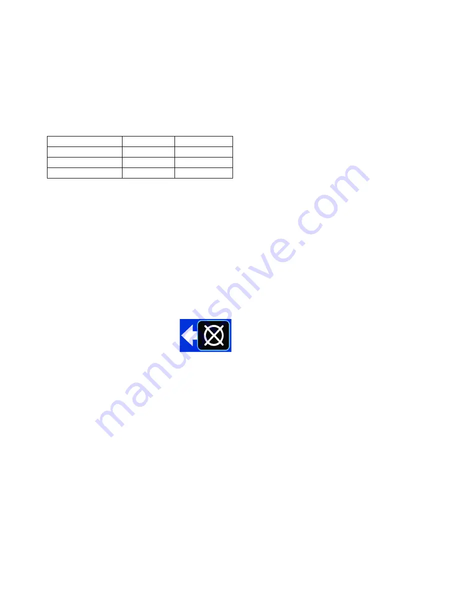
Press the reset button (LEFT ARROW 
button) once to clear the buzzer. Press 
and hold the reset button for 3 
seconds to clear the alarm and switch 
the controller to idle.

Low Level Alert State

Run mode continues

Low level LED is on (B, F

IG

. 1)

System LED is on (A, F

IG

. 1)

Output 2 in ON

Low Level Alarm State

Pump operation is immediately disabled

Low level LED is on (B, F

IG

. 1)

System LED flashes red (A, F

IG

. 1)

Output 2 is ON

Audible alarm

Screen shows alarm information

Clear Alarm Buzzer

Press reset (LEFT ARROW button) to silence the 
buzzer.

The buzzer sounds again after 4 hours if the low level 
condition is not resolved. The buzzer also sounds again 
when power is cycled.

Clear Low Level Alarm 

Filling the reservoir resolves a low level sensor and low 
level switch condition, and the level sensor and level 
switch will self-clear.

Hold the reset button for at least 5 seconds to remove 
the low level alarm from the controller. 

For more details regarding a specific alarm, see 

Alarm 

Types

, page 18 and 

Troubleshooting

, page 21.

End Configuration

ON time (min) OFF time (min)

Pressure System

7

1

Timer System

2

1

Cycle System

2

1

Summary of Contents for 26A814

Page 1: ...ed lubrication system For professional use only Not approved for use in explosive atmospheres or hazardous classified locations Model 26A814 Important Safety Instructions Read all warnings and instruc...

Page 2: ...etup and Data Entry 12 Change Settings 12 Low Level 13 Lock 14 Start Up 14 Output 2 14 System 14 Additional Advanced Features 14 Program Settings 15 Operation 16 Main Screens 16 Test Mode 17 Alarms 17...

Page 3: ...See Technical Specifications in all equipment manuals Read fluid and solvent manufacturer s warnings For complete information about your material request Safety Data Sheets SDSs from distributor or r...

Page 4: ...the cursor in the display one field to the left It also navigates back to the previous screen and cancels parameter change If the pump is lubricating pressing this button cancels the event and the pum...

Page 5: ...Component Identification 3A7031A 5 FIG 2 GLC X Controller Back Identification Label...

Page 6: ...de for selecting and installing system components Key A Lubrication Controller B Solenoid Value C Pump Module D Ignition Switch E High Pressure Lubricant Supply Lines F Injector Banks G In line 15A Fu...

Page 7: ...ication system could result in serious injury including skin injection and amputation The Lubrication Controller has an automatic timer that activates the pump lubrication system when power is connect...

Page 8: ...System Configuration 8 3A7031A System Configuration To determine the required configurations needed refer to the following pages Injector System FIG 6 Injector System Configuration...

Page 9: ...System Configuration 3A7031A 9 Divider Valve FIG 7 Divider Valve System Configuration...

Page 10: ...arity 1 Pump Motor 2 Auxiliary Alarm 3 Auxiliary Alarm ground 4 Sensor power 1 5 Sensor power 2 6 Voltage source 7 Pump Motor ground 8 Input 2 ground 9 Input 2 LOW LEVEL Input 10 Voltage source ground...

Page 11: ...Sensor Wiring Configurations 3A7031A 11 Sensor Wiring Configurations Dry Contact Switch Analog Sensor Source PNP Switch 2 or 3 Wire Type FIG 9 FIG 10 FIG 11...

Page 12: ...uently the GLC X lubricates the product Select either Timer Interval or Machine Count Interval Timer Interval This sets up how frequently lubrication occurs Interval defines the time between lubricati...

Page 13: ...ems Count defines the number of cycle inputs required per lubrication event Alarm Timeout defines the maximum allowable time to accumulate cycle counts Solenoid Failure Alarm if enabled an alarm displ...

Page 14: ...se the arrow buttons to enter the PIN After entering the last digit press the RIGHT ARROW button to accept the PIN If the PIN is correct the device enters SETUP If the PIN is incorrect the device retu...

Page 15: ...detected during idle time Low Level page 13 Low Level Type Paddle Low Level Switch Low Level Sensor Paddle Low Level Alert Threshold Recommended 10 00 to 99 Requires Alarm Alert Setting of zero disab...

Page 16: ...e following illustrations for examples of typical operation screens FIG 12 Lubrication Event Pressure Switch FIG 13 Lubrication Event Pressure Sensor FIG 14 Lubrication Event Cycle FIG 15 Lubrication...

Page 17: ...System LED is on A FIG 1 Output 2 in ON Low Level Alarm State Pump operation is immediately disabled Low level LED is on B FIG 1 System LED flashes red A FIG 1 Output 2 is ON Audible alarm Screen show...

Page 18: ...broken or plugged lines Confirm that the pump is operating correctly Confirm that the vent valve is operating correctly Inspect the wiring pressure switch and sensor Confirm that sufficient time was p...

Page 19: ...he machine use is low Confirm that the controller settings are correct for machine usage The cabling to machine count is broken A23 Solenoid Failure No Symbol The solenoid valve used to control the lu...

Page 20: ...e and recycle it in a responsible manner Dismantle and recycle Remove motors circuit boards LCDs liquid crystal displays and other electronic components Recycle according to applicable regulations Do...

Page 21: ...rication event Incorrect or loose wiring Confirm current is being delivered to the pump during a lubrication event Verify that your machine has been wired correctly Refer to Installation page 7 Contro...

Page 22: ...Accessories Dimensions Part Number Description 26A882 GLC X Harness Kit 26A883 GLC X to CDS Harness Kit 26A884 CDS Harness Kit...

Page 23: ...ing Hole Layout 3A7031A 23 Mounting Hole Layout NOTICE Pre drill and use only designated mounting holes in Lubrication Controller box Failure to use designated mounting holes can cause circuit board d...

Page 24: ...non condensing Materials of Constructions Enclosure Material ABS Membrane Material Polyester Lens Material Polycarbonate Input Contact Power Source DC 9 30 VDC Power Consumption 1 W no load 15 A max...

Page 25: ...ce and 2 this device must accept any interference received including interference that may cause undesired operation Changes or modifications not expressly approved by the party responsible for compli...

Page 26: ...n material or workmanship repairs will be made at a reasonable charge which charges may include the costs of parts labor and transportation THIS WARRANTY IS EXCLUSIVE AND IS IN LIEU OF ANY OTHER WARRA...

Reviews: