309280
Rev. A
First choice when
quality counts.
t
INSTRUCTIONS-PARTS LIST
INSTRUCTIONS
This manual contains important
warnings and information.
READ AND KEEP FOR REFERENCE.
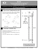
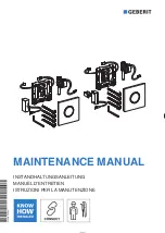
Ultra–Flo Shot Metering Dispenser
2500 psi (17.2 MPa, 172.4 bar) Maximum Fluid Working Pressure
The Ultra–Flo Shot Metering Dispensers listed below
are described in this manual. These units are specifi-
cally designed to be used with robotic equipment. Use
of the Graco Ultra–Flo Shot Metering Dispenser with
non–robotic equipment can result in personnel injury or
damage to equipment.
List of Models
Part No. 243348, Series A
Without board for Precision Swirl
Part No. 243349, Series A
With board for Precision Swirl
Part No. 244816, Series A
Without board for Precision Swirl and
without temperature conditioning jacket
Part No. 244817, Series A
With board for Precision Swirl and
without temperature conditioning jacket
TI0853
Motor Drive
provided by other
manufactures.
GRACO INC.
P.O. BOX 1441 MINNEAPOLIS, MN 55440–1441
E
COPYRIGHT 2001, GRACO INC.
Graco Inc. is registered to I.S. EN ISO 9001