background image

9

307212

Operation

7.

Adjust the fluid regulator to the desired setting.

a.

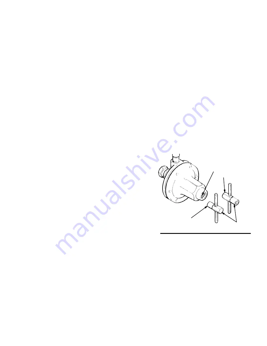
Spring Operated Regulators Only (see Fig. 3).
The regulator can be adjusted in two ways:

Using the male end (B) of the regulator
key (24), turn the socket–head adjustment
screw (19) fully clockwise. Verify that the
pressure setting has not changed.

Using the female end (A) of the regulator
key (24), turn the adjustment screw (12)
counterclockwise to return to the desired
pressure setting.

b.

Air Operated Regulator Only.  The regulator
can be adjusted in two ways:

Close the air regulator bypass valve and
open the outlet valve at the air regulator.
Verify that the pressure setting has not
changed.

Adjust the air regulator to return to the
desired fluid pressure setting.

Regulating Fluid Pressure

Spring Operated Regulator

1.

Close the regulator: engage the female end (A) of
the key (24) with the adjusting screw (12) and turn
it counterclockwise to relieve the spring tension.
See Fig. 3.

2.

Start the pump and open the fluid regulator’s inlet
ball valve to admit fluid to the regulator. See Fig. 1.

3.

Turn the key (24) clockwise to increase fluid pres-
sure. See Fig. 3. Adjust for the desired spray
pattern.

NOTE: If using a fluid pressure gauge, reduce the
regulator pressure before partially relieving pressure in
the gun hose, to ensure a correct gauge reading. Then
increase regulator pressure to the desired setting.

Air Operated Regulator

1.

Start the pump and open the fluid regulator’s inlet
ball valve to admit fluid to the regulator. See Fig. 2.

2.

Increase the air pressure to obtain the desired fluid
pressure. Adjust for the desired spray pattern.

NOTE: If using a fluid pressure gauge, reduce the
regulator pressure before partially relieving pressure in
the gun hose, to ensure a correct gauge reading. Then
increase regulator pressure to the desired setting.

NOTE: Make sure the air bleed hole in the air line
fitting (29) is not plugged. Refer to page 12.

For the best results, use an air regulator with at least a
2 in. (51 mm) diameter diaphragm to control this fluid
regulator.

12

24

B

A

Fig. 3

Summary of Contents for 214706

Page 1: ...ulate fluid pressure in low pressure systems only Fluid Flow up to 3 GPM 11 liters min Instructions Parts List 307212AK Important Safety Instructions Read all warnings and instructions in this manual Save these instructions See page 3 for List of Models and Table of Contents ...

Page 2: ...2 307212 Table of Contents Models 3 Warnings 5 Installation 6 Operation 8 Troubleshooting 11 Service 12 Parts 16 Dimensions 21 Technical Data 22 Performance Charts 23 Warranty 24 Graco Information 24 ...

Page 3: ...t compatible with US standard pitch Fluid housing coated with PTFE polymer These models are and certified The fluid supply system s main line pressures often exceed the pressure range of the gauge supplied with regulators 214706 243414 255374 and 24A082 Exposing this gauge to excessive pressure can damage the gauge causing inaccurate readings and the needle will not return to zero This damage is n...

Page 4: ...4 307212 Notes ...

Page 5: ...e equipment Use the equipment only for its intended purpose If you are uncertain about usage call your Graco distributor Do not alter or modify this equipment Use only genuine Graco parts and accessories Check the equipment daily Repair or replace worn or damaged parts immediately Do not exceed the maximum working pressure of the lowest rated system component Use fluids that are compatible with th...

Page 6: ...ILTER REGULATOR Spring Operated Installation Models 214895 214706 243414 217314 221118 255374 and 24A082 Pilot Regulator Air Supply Line Air Operated Installation Model 214980 shown OUTLET BALL VALVE AIR SUPPLY AIR FILTER MOISTURE SEPARATOR REGULATORS INLET BALL VALVE Fig 1 Fig 2 AIR REGULATOR BYPASS VALVE FLUID REGULATOR ...

Page 7: ...Thoroughly flush the system to remove metal chips and other contaminants and to check for leaks Installing the Fluid Regulator 1 Remove the temporary plumbing and install one regulator for each spray gun See the Dimension al Drawing on page 21 for regulator dimensions Mount the regulator in a vertical position as shown in Figs 1 and 2 for the best flow and minimum pigment settling The gauge if use...

Page 8: ...mp and relieve fluid pressure in the system by triggering the gun and opening the back pressure regulator or other bypass valve 3 Never exceed the maximum working pressure of the lowest rated system component Remove the gauge if the flushing pressure will exceed the gauge range 4 Open the fluid regulator fully a Spring Operated Regulators Only see Fig 3 The regulator can be fully opened in two way...

Page 9: ...ing tension See Fig 3 2 Start the pump and open the fluid regulator s inlet ball valve to admit fluid to the regulator See Fig 1 3 Turn the key 24 clockwise to increase fluid pres sure See Fig 3 Adjust for the desired spray pattern NOTE If using a fluid pressure gauge reduce the regulator pressure before partially relieving pressure in the gun hose to ensure a correct gauge reading Then increase r...

Page 10: ...10 307212 Notes ...

Page 11: ...ks from under cap Loose cap 7 Tighten screws 1 in sequence shown in Service section Worn gasket 26 Replace gasket Pressure creeps above setting Damaged or clogged air regulator or line 214980 only Clear obstruction in line service regu lator if necessary Damaged diaphragm 22 Replace diaphragm Seat leaking 16 Replace ball 20 seat and gasket 15 Pressure drops below setting Damaged or clogged air reg...

Page 12: ...pring 3 valve stem 9 and gasket 21 from the stem housing 18 11 Thoroughly clean and inspect all parts Replace any parts that appear to be worn or damaged 12 Place stem housing 18 in a vise One at a time place the gasket 26 diaphragm 22 white PTFE side down toward the bottom housing and washer 17 on the stem housing 18 Secure them with the jam nut 13 Torque the jam nut onto the stem housing to 21 3...

Page 13: ...e tightening sequence Tighten evenly to 7 10 in lb 0 8 1 1 N m then retorque to 125 in lb 14 N m three times consecu tively to compensate for diaphragm relaxation 5 2 4 6 1 3 BOTTOM VIEW Air Bleed Hole Fig 4 1 3 2 Torque to 21 35 ft lb 28 47 N m 1 1 Torque to 21 25 ft lb 28 34 N m 2 Torque to 23 27 ft lb 31 36 N m 3 ...

Page 14: ...26 11 Remove the spring 3 valve stem 9 and gasket 21 from the stem housing 12 Thoroughly clean and inspect all parts Replace any parts that appear to be worn or damaged 13 Place stem housing 18 in a vise One at a time place the gasket 26 diaphragm 22 white PTFE side down toward bottom housing dia phragm 25 on Models 217314 and 221118 only and washer 17 on the stem housing 18 Secure them with the j...

Page 15: ...9 18 4 20 1 5 2 4 6 1 3 BOTTOM VIEW PET NOTE Numbers indicate tightening sequence Tighten evenly to 7 10 in lb 0 8 1 1 N m then retorque to 125 in lb 14 N m three times consecutively to compensate for diaphragm relaxation Fig 5 1 3 4 2 Torque to 21 25 ft lb 28 34 N m 1 Torque to 21 35 ft lb 28 47 N m 2 2 Torque to 23 27 ft lb 31 36 N m 3 1 PTFE side down toward housing 6 4 4 3 5 ...

Page 16: ...855 NUT adjustment 1 12 176691 SCREW adjustment 1 13 171858 NUT jam special 1 14 176692 WASHER flat 1 15 171860 GASKET seat 1 16 112366 SEAT valve tungsten carbide 1 15F236 SEAT valve tungsten carbide 1 17 171862 WASHER diaphragm 1 18 187879 HOUSING stem 1 19 176136 SCREW adjustment 1 20 112365 BALL tungsten carbide 1 21 171867 GASKET 1 22 171868 DIAPHRAGM PTFE with nylon fabric Buna N base 1 23 2...

Page 17: ...ining 1 11 171855 NUT adjustment 1 12 176691 SCREW adjustment 1 13 171858 NUT jam special 1 14 176692 WASHER flat 1 15 171860 GASKET seat 1 16 15F236 SEAT valve tungsten carbide 243414 and 24A082 1 15V292 SEAT valve tungsten carbide 255374 only 1 17 171862 WASHER diaphragm 1 18 187879 HOUSING stem 1 19 176136 SCREW adjustment 1 20 112365 BALL tungsten carbide 1 21 171867 GASKET 1 22 171868 DIAPHRA...

Page 18: ...6691 SCREW adjustment 1 13 171858 NUT jam special 1 14 176692 WASHER flat 1 15 171860 GASKET seat 1 16 112366 SEAT valve tungsten carbide 1 15F236 SEAT valve tungsten carbide 1 17 171862 WASHER diaphragm 1 18 187879 HOUSING stem 1 19 176136 SCREW adjustment 1 20 112365 BALL tungsten carbide 1 21 171867 GASKET 1 22 180052 DIAPHRAGM PTFE 1 23 235209 UNION swivel 3 8 npsm 1 24 215393 KEY regulator 1 ...

Page 19: ...58 NUT jam special 1 15 171860 GASKET seat 1 16 112366 SEAT valve tungsten carbide 1 15F236 SEAT valve tungsten carbide 1 17 171862 WASHER diaphragm 1 18 187879 HOUSING stem 1 20 112365 BALL tungsten carbide 1 21 171867 GASKET 1 22 171868 DIAPHRAGM PTFE with nylon fabric Buna N base 1 23 235209 UNION swivel 3 8 npsm 1 26 172132 GASKET cellulose fibre 1 27 187875 GAUGE pressure stainless steel 30 p...

Page 20: ...CREW retaining 1 13 171858 NUT jam special 1 15 171860 GASKET seat 1 16 112366 SEAT valve tungsten carbide 1 15F236 SEAT valve tungsten carbide 1 17 171862 WASHER diaphragm 1 18 187879 HOUSING stem 1 19 197213 STUD mounting 2 20 112365 BALL tungsten carbide 1 21 171867 GASKET 1 22 171868 DIAPHRAGM PTFE with nylon fabric Buna N base 1 23 235209 UNION swivel 3 8 npsm 1 26 172132 GASKET cellulose fib...

Page 21: ... 1 76 44 7 mm 1 8 46 mm 3 8 npsm female INLET 3 8 19 ISO male Model 243414 only 3 65 93 mm DIA 3 8 npt f OUTLET 3 8 19 ISO female Model 243414 only 1 4 npt GAUGE PORT 10 25 260 mm 1 4 npt AIR INLET Model 214980 only 3 8 npsm female ADAPTER OUTLET Models 217314 and 221118 only ...

Page 22: ...414 244375 255374 24A082 5 100 psi 30 700 kPa 0 3 7 0 bar Model 214980 0 30 psi 0 210 kPa 0 2 bar Maximum Flow Capacity 3 gpm 11 liters min with 70 cps fluid at 200 psi 1 4 MPa 14 bar inbound pressure Wetted Parts Tungsten Carbide Acetal Resins PTFE 304 316 Series Stain less Steel Nylon PET Canadian Registration Number CRN Alberta 0C4155 2 Ontario 0C4874 5 Models 214895 214706 217314 221118 and 21...

Page 23: ...82 kPa bar psi 250 PSI INLET 600 CPS 250 PSI INLET 65 CPS 250 PSI INLET 65 CPS 100 PSI INLET 600 CPS 100 PSI INLET 65 CPS 250 PSI INLET 600 CPS 250 PSI INLET 65 CPS 100 PSI INLET 600 CPS 100 PSI INLET 65 CPS 250 PSI INLET 600 CPS 250 PSI INLET 65 CPS 100 PSI INLET 600 CPS 100 PSI INLET 65 CPS 250 PSI INLET 600 CPS 250 PSI INLET 65 CPS 0 7 1 4 2 1 2 8 3 4 4 1 4 8 5 5 6 2 7 0 0 7 1 4 2 1 2 8 3 4 4 1...

Page 24: ... remedy including but not limited to incidental or consequential damages for lost profits lost sales injury to person or property or any other incidental or consequential loss shall be available Any action for breach of warranty must be brought within two 2 years of the date of sale Graco makes no warranty and disclaims all implied warranties of merchantability and fitness for a particular purpose...

Reviews: