12
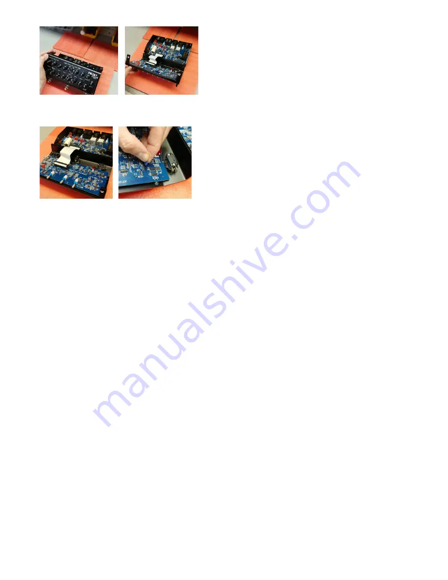
5. Now refer to the jumper location diagram on the following
page to adjust the jumpers you wish.
6. To move a jumper, use tweezers or your fingernails to
gently pull the jumper off of its header pins. To reposition
the jumper, double check the diagram, then gently press
the jumper back down in the correct location.
7. When you are finished adjusting the jumpers, make sure
there are no loose jumpers or any other junk lying around
inside.
8. Then carefully reassemble the top and bottom chassis,
making sure to let the ribbon cable fold easily back in
place. If there is any tension or something isn’t fitting
properly, carefully pull the top and bottom back apart and
inspect for interference.
9. Once you have put the unit back together, replace the 4
screws, making sure they go in straight and true. You may
need to nudge the top panel back and forth a bit to ensure
the holes in the top panel chassis line up evenly with the
inner threaded holes.
10. Do not tighten the screws until all 4 are cleanly started in
the threads. Take your time and remember, cross-threading
is a crime.
If you get stuck or something doesn’t look right, call us right
away and we’ll get you taken care of.
10.1 INTERNAL JUMPER LOCATIONS
Lower PC board Locations
J2 - Sets the CH1 instrument input gain range. Options are LO
(3-48dB) and HI (17-62dB). This is set to
LOW
at factory.
J6 and J7- Configures 12V power, which can be applied to
either channel’s tip, ring, or set to off. Set these according to
how your microphone / instrument is wired. This jumper is set
to
OFF
at the factory, with the jumper simply pressed down on
one pin.
J15 - configures DI output mode when the preamp is in
A/B mode and DI source switch is set to MIX. DUAL ISO
mode (jumper center and left) keeps both DI outputs active
regardless of which channel is selected. EXCLUSIVE output
mode (jumper center and right) mutes the inactive channel’s DI
output. This is set to
DUAL ISO
mode at the factory.
J14 and J17 - These jumpers apply a signal pad to the insert
send, one for each channel. There are 3 settings: OFF, -6dB and
-16dB. These are set to
-6dB
from the factory.
J18 - Insert Return, can be set to MONO or STEREO, depending
on how you want the FX insert to operate. Set to
MONO
at the
factory.
J19 - Insert Send CH1, can be CH1 or MIX. Set to
MIX
at the
factory.
Upper PC board Locations
J3 - enables / disables the Boost control on CH1. Set to
ENABLE
at the factory.
J11 and J13 - adjusts the EQ’s high shelf corner frequency at
either 1kHz or 2kHz. Set to
2kHz
at the factory.
J25 and J26 - adjusts the EQ’s low shelf corner frequency at
either 150Hz or 250Hz. Set to
250Hz
at the factory.
J31 - Activates / deactivates the CH2 variable phase control. Set
to
OFF
at the factory.
J32 - Selects CH1 preamp LOW or HIGH gain setting. LOW
(+17dB and +62dB) and LOW (+22dB and +63dB). Set to
LOW
at the factory.


