background image

22

TROUBLESHOOTING

OPERA

TION

ASSEMBL

Y /


INST

ALLA

TION

SAFETY

 / 

SPECIFICA

TIONS

GETTING

 ST

ARTED

MAINTENANCE

 / 

REP

AIR

REPAIR (CONTINUED)

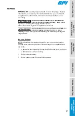
Replace Gears

1. Turn the pump OFF and disconnect from power.
2. Using 5mm hex wrench, remove the gear coverplate and O-ring (see

Figure 12).

4. Remove the gears.
5. Inspect gears for wear and damage. Replace,

as necessary.

6. Wipe the gear cavity with a clean cloth.
8. Replace the gears.
9. Make sure the gear coverplate O-ring is securely in place.

Tighten the coverplate to the housing.

10. Clean Bypass poppet (see Figure 13).

Figure 12

Gears

Coverplate Seal O-ring

Coverplate

Summary of Contents for G20-012AD

Page 1: ...20 GPM 76 L min 12V dc Fuel Transfer Pump Models G20 012PX G20 012MD G20 012AD PATENT PENDING Product Owner s Manual 922138 01 Rev A 09 2019 ...

Page 2: ...eps Heavy_Hazard eps Hot_surface eps Recycle eps Resp_protection1 eps Resp_protection2 eps BEFORE YOU BEGIN Fueling Requirements This fuel pump is designed tested and approved for use with gasoline blends up to E15 diesel fuel blends up to B20 and kerosene Please take all due precautions when handling these flammable liquids Do not use this pump for dispensing any fluids other than those for which...

Page 3: ...warnings below To prevent physical injury or property damage observe precautions against fire or explosion when dispensing fuel Do not operate the system in the presence of any source of ignition including running or hot engines lighted tobacco products gas or electric heaters or any type of electronic device A spark can ignite fuel vapors Observe precautions against electrical shock when operatin...

Page 4: ...22 F to 131 F 30 C to 55 C Max Surface Temperature 320 F 160 C Operating Pressure 12 PSI 0 82 bar Input 12V dc Current Draw 34 amps Motor 2000 RPM 38 hp Motor Approval cULus Listed Class I Div 1 IECEx ATEX Zone 1 cULus Listed Class I Div 2 Motor Protection 40 amp circuit breaker Cord N A 18 ft 5 5 m of 12 ga Fuse 40 amp Inlet 1 in NPT Outlet 1 in NPT Hose Type N A Buna N Electrically Conductive Di...

Page 5: ...ETTING STARTED 6 ASSEMBLY INSTALLATION SAFETY SPECIFICATIONS Figure 1 SPECIFICATIONS CONTINUED G20 012PX G20 012MD G20 012AD Dimensions A Pump Assy Width 9 20 in 23 36 cm B Pump Assy Height 9 24 in 23 46 cm C Pump Assy Depth 11 62 in 29 51 cm B A C ...

Page 6: ...Atmospheres Part 1 Equipment protected by flameproof enclosures d IECEx specific conditions of use 1 Flameproof joints are not intended to be repaired 2 The special fasteners used as securing bolts for the end bell are made of Class 10 9 type fasteners The special fasteners used for electrical cover plate attachment are made of Class A2 70 type fasteners ATEX Information Marking string Mfg Date B ...

Page 7: ...NOTES MAINTENANCE REPAIR TROUBLESHOOTING OPERATION ASSEMBLY INSTALLATION SAFETY SPECIFICATIONS GETTING STARTED 8 ...

Page 8: ...g on the top of the pump and pour a small quantity of motor oil into the gear cavity Replace and try again A foot valve with pressure relief may be needed to maintain prime Install Tank Adapter and Suction Pipe 1 Wrap lower threaded end of the tank adapter with three or four turns of thread tape see Figure 2 Using a wrench tighten the adapter snugly into the fuel tank NOTE For Aluminum Tank Instal...

Page 9: ...ng a 4mm Hex wrench install nozzle cover using 1 M6 1 0 x 14mm BHCS in lower hole see Figure 5 NOTE For model G20 012PX only DO NOT install nozzle cover until after wiring is completed Install 1 in NPT Outlet Adapter 1 Remove plastic plug from outlet port of pump 2 Install 222 O ring into outlet port Make sure O ring is seated properly 3 Using a 5mm Hex wrench install the 4 M6 1 0 x 20mm SHCS into...

Page 10: ...and thread into outlet port Tighten securely using an adjustable wrench 2 Wrap opposite end of hose with three or four turns of thread tape and thread into nozzle Tighten securely using an adjustable wrench 3 Place the nozzle into the nozzle holder on the end of the pump motor housing Note that the nozzle cannot be placed in the holder unless the pump switch is OFF see Figure 9 Outlet Adapter M6 1...

Page 11: ...ON 2 locations such as portable fuel tanks trailers etc Connection method to a battery will depend upon the application Installation Replacement Power Cord DIV 2 ONLY For installation in unclassified areas the supplied power cord fuse and strain relief grip may be used NOTE These components have not been evaluated as part of the UL Listed Equipment and are not intended for use in a Hazardous Class...

Page 12: ...avity see Figure 7 an external ground can be used instead When using the external ground for the G20 012PX Zone 1 or 2 the installer must use a ground wire with a minimum cross sectional area of 4mm2 To use external ground remove green ground screw from electrical cavity and install in location shown see Figure 7a Figure 7a Only for G20 012AD and G20 012 MD models Black Wires Green Ground Screw St...

Page 13: ...rip 3 to 4 inches of outer insulation from end of power cord DO NOT CUT INSULATION OF INNER WIRES Next using wire strippers remove 1 4 in of insulation from the black and red power cord wires 2 First disconnect vehicle wiring from the negative ground terminal of the battery and then connect as follows Using wire strippers carefully strip 1 4 in of insulation from both ends of the fuse assembly wir...

Page 14: ...s not contaminated with debris Tighten loose tank lids regularly Dispensing Fuel 1 Remove the nozzle from holder and insert into receiving tank Turn the pump on by pushing the switch lever up Squeeze the handle to start fuel flow When done release the nozzle handle turn the pump off and return the nozzle to its holder IMPORTANT This pump is designed to be self priming If fuel is not delivered with...

Page 15: ...aded the protective device trips and opens the circuit This feature protects the motor from damage and must be reset manually 2 To reset turn switch lever OFF and then back ON see Figures 9 and 10 3 If the protective device trips again quickly disconnect from power source before attempting to troubleshoot the problem Follow the instructions provided in the Troubleshooting section of this manual 4 ...

Page 16: ... wire to positive ungrounded side of battery Motorshaft should turn clockwise 2 Poor connections or low voltage 2 Make sure electrical connections are secure Check battery voltage 3 Fuel level low 3 Fill tank 4 Strainer clogged or defective 4 Remove pump coverplate Remove and clean strainer Install again 5 System air leak 5 Tighten all pump fittings and connections Inspect suction pipe for leaks o...

Page 17: ...ct suction pipe Clean or replace as necessary 5 System air leak 5 Tighten all pump fittings and connections Inspect suction pipe for leaks or damage Replace as necessary 6 Using off the shelf automatic nozzle 6 Factory supplied automatic nozzle is recommended Motor stalls when operating in bypass mode 1 Motor protector activated 1 Turn off switch Allow motor to cool then turn on switch 2 Wiring de...

Page 18: ...3 Motor damaged 3 Replace pump Overheating of motor 1 Duty cycle too long 1 Pump operation should not exceed the standard duty cycle of 30 minutes ON and 30 minutes OFF Allow the pump to cool for 30 minutes 2 Running too long in bypass mode 2 Limit bypass operation to 10 minutes 3 Strainer clogged 3 Remove strainer coverplate Remove and clean strainer Install again 4 Suction pipe clogged or damage...

Page 19: ...BEGIN Fueling Requirements at front of manual may damage the pump Use of the pump with unauthorized fluids will void the warranty Clean or Replace Strainer 1 Turn the pump off and disconnect from power Using 5mm hex wrench remove the coverplate O ring and inlet strainer and inspect for damage or clogs see Figure 11 Clean the strainer with a soft bristled brush and solvent If the strainer is very d...

Page 20: ...ing Never apply electrical power to the system when any of the coverplates are removed Avoid prolonged skin contact with petroleum fuels Use protective goggles gloves and aprons in case of splashing or spills Change saturated clothing and wash skin promptly with soap and water Service O rings NOTE A Wet Seal Kit contains all seals for your pump and should be on hand when performing repairs Old sea...

Page 21: ...ng 5mm hex wrench remove the gear coverplate and O ring see Figure 12 4 Remove the gears 5 Inspect gears for wear and damage Replace as necessary 6 Wipe the gear cavity with a clean cloth 8 Replace the gears 9 Make sure the gear coverplate O ring is securely in place Tighten the coverplate to the housing 10 Clean Bypass poppet see Figure 13 Figure 12 Gears Coverplate Seal O ring Coverplate ...

Page 22: ...ith a 10mm Hex wrench remove the pipe plug from the coverplate and remove the bypass poppet spring O ring bypass poppet and orifice seal see Figure 13 4 Inspect the O ring and replace as necessary NOTE Replace O ring if damaged swollen or loose fitting see Wet Seal Kit 5 With a clean cloth wipe the poppet components and replace 6 Before seating coat O ring with light grease 7 Install coverplate Fi...

Page 23: ...m SHCS on gear coverplate and 1 M6 x 35mm SHCS located on back of pump housing Separate pump housing and fittings from drive shaft see Figure 14 3 Remove motor shaft seal from pump housing see Figure 14 4 Press a new motor shaft seal evenly in the pump housing until seated Lubricate the seal with a lightweight motor oil 5 Reinstall pump housing with gear coverplate gears and fittings Figure 14 Mot...

Page 24: ... and nozzle cover 4 Remove the 4 M6 SHCS and electrical coverplate from the motor housing 5 Remove the 1 10 truss head screw and switch bracket with switch assembly see Figure 15 6 Unscrew both 6 machine screws and remove the switch assembly from the switch bracket 7 Unscrew both blade terminals and remove red pump wires from the back of the switch see Figures 15 and 16 Take note of which wire is ...

Page 25: ...e following information The model number of your pump The serial number or manufacturing date code of your pump Part descriptions and numbers For warranty work always be prepared with your original sales slip or other evidence of purchase date Do not return the pump or parts without prior approval from the GPI Customer Service Department Due to strict government regulations GPI cannot accept parts...

Page 26: ...1 Gasket 1 6 Power Cord Kit 110242 01 Power cord 12 2 1 Strain relief 1 Available as part of kit only IMPORTANT Please contact GPI before returning any parts It may be possible to diagnose the trouble and identify needed parts in a telephone call GPI can also inform you of any special requirements you will need to follow for shipping fuel dispensing equipment IMPORTANT In order to preserve the UL ...

Reviews: