


OPERATION MANUAL - Trailer Refrigeration Unit
arktik 1600N • 1600 N/T • 2000N • 2500N • 2000P • 2500 N/K • 2000 P/K
50.04.504 / 1.0
Copyright by GOVI GmbH 2021. The reproduction of this document or any part thereof is prohibited. We reserve the right to make technical changes during the course of further developments.
16
Page
1
2
1. Main cover
2. Evaporator (with refrigerant
in the system)
3. Protection cover
4. Air intake (do not obstruct!)
5. Air outlet (do not obstruct!)
6. Condenser (with refrigerant
in the system)
Fig. 5-2 Overview of the trailer refrigeration unit
Main cover (1)
Evaporator (2) and
condenser (6)
Protection cover (3)
and setting of nominal
temperature
Air intake (4) and
air outlet (5)
The main cover (1) covers the outer parts of the trailer
refrigeration unit.
In the evaporator (2) heat is absorbed by the refrigerant, which is
released again in the condenser (6).
The protection cover (3) shields the control unit from harsh weather
and impedes unintended changes of the settings.
The nominal temperature is set according to
section 9.2 Setting
Nominal Temperature.
The air intake (4) and air outlet (5) must always be kept free.
They must not be covered or obstructed.
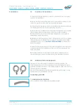
6
4
5
3