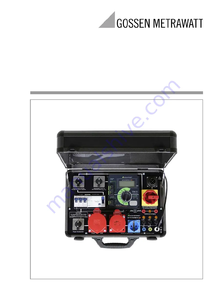
Operating Instructions
METRA
TESTER 5+
⏐
3P
Workshop Test Panel for Testing Devices per DIN VDE 0701-0702 and DIN VDE 0104
3-349-414-03
6/2.11
Page 1: ...Operating Instructions METRATESTER 5 3P Workshop Test Panel for Testing Devices per DIN VDE 0701 0702 and DIN VDE 0104 3 349 414 03 6 2 11 ...
Page 2: ...act surface for finger contact 8 Plug connector for mains cables 9 Mains emergency stop switch undervoltage trigger can be connected at zero setting 10 Durchgang continuity indicator lamp 11 Connector sockets for continuity test with max 33 V AC 12 RCD residual current circuit beaker 4 25 A 0 03 A 13 Three circuit breakers B16 A 14 Polarity reversing switch 15 CEE socket 3P N PE 32 A 230 400 V max...
Page 3: ...r Resistance for Protection Class I Devices 12 6 2 Measuring Insulation Resistance 13 6 3 Measuring Protective Conductor Resistance 15 6 3 1 Equivalent Leakage Current 15 6 3 2 Differential Current Measurement for Protection Class I Devices 16 6 4 Measuring Contact Current 17 6 4 1 Contact Current Measurement Differential Current 17 6 4 2 Testing in Accordance with the Direct Method 17 6 5 Measuri...
Page 4: ... of operating voltage and current consumption at devices under test Beyond this the protective conductor at the mains connection can be tested for the absence of voltage and line voltage can be measured Extension cables can be tested after connecting the VL2 E accessory 2 Safety Precautions The test case is equipped with a METRATESTER 5 test instrument and has been manufactured and tested in accor...
Page 5: ...ore metrological testing is performed If the test case and or its connector cables demonstrate visible damage no longer function have been stored for a lengthy period of time under unfavorable conditions or have been subjected to excessive stress during transport it must be assumed that hazard free operation is no longer possible If this is the case remove the test case from service and secure it ...
Page 6: ...en connect the test case to the mains Set the mains switch 9 and the RCD residual current circuit breaker 12 to EIN on According to the manufacturer the emergency stop switch may generate minor humming noises with the U coil in certain armature positions If this is the case quickly turn the emergency stop switch on and off several times When connected via the 5 pole CEE mains adapter 23 indicator ...
Page 7: ...tlets the PE socket 20 and the jack 4 Immediately disconnect the test case from the mains and arrange to have the fault eliminated at the mains connection Voltage in the mains protective conductor also results in incorrect measured values when testing for the absence of voltage in accordance with DIN VDE 0701 0702 see section 6 4 1 4 3 Measuring Line Voltage Set the measuring function selector swi...
Page 8: ... switches Insulation resistance followed by protective conductor or equivalent leakage current Otherwise leakage current during operation differential current protection class I devices Contact current for protection class II devices Safety extra low voltage only at point of connection of safety extra low voltage generated in the DUT 4 Function Test 5 Labeling inspection 6 Documentation 5 1 Protec...
Page 9: ...gle or Multi Phase Connection without Plug Connect the DUT for example to the earthing contact outlet or to the connec tor sockets in the case of loose wire ends Switch the DUT on Mains Connection Sockets To Accessible Metal Parts Either Mains Connection Sockets Switch the DUT on Either ...
Page 10: ...Stationary Devices for Protective Conductor Testing via the Supply Mains 5 5 Data Processing Equipment Either Mains Connection Sockets Switch the DUT on To Mains Protective Conductor Mains Connection Sockets Switch the DUT on Either ...
Page 11: ...the test case as well as before each new test NETZ VDE switch 1 Set to VDE METRATESTER 5 function selector switch 6 Set to IEA 20 mA Polarity reversing switch 14 Set to 1 Measuring selector switch L1 L2 L3 2 Set to L1 5 8 Setting the Switches at the Device Under Test Connect the device under test to the test case and switch all of its functions on making sure that for example thermostat contacts a...
Page 12: ...his end connection must first be established from the protective conductor socket 4 at the METRA TESTER 5 to a protective conductor which has been previously tested for the absence of voltage for example at an outlet within the electrical system which is connected with the protective conductor of the DUT When testing in accordance with DIN VDE 0701 0702 DUTs with external connections such as data ...
Page 13: ...ays If this is only possible after applying mains voltage testing in accordance with section 6 3 2 section 6 4 1 must be performed If there is any doubt about performing measurement with insulation voltage for example at electronic devices measurement must also be performed in accordance with section 6 3 2 section 6 4 1 It must be assured that all switches thermostats etc are closed Attention Do n...
Page 14: ...class II and III devices as well as for battery powered devices This test is omitted for protection class III and battery powered devices which fulfill the following conditions Nominal power 20 VA Nominal voltage 42 V Batteries must be disconnected during testing of battery powered devices Note In the event of long term short circuiting in the 20 MOhm range measuring current is reduced after appro...
Page 15: ...ection is the same as for insulation resistance measurement Ð Set the NETZ VDE switch to VDE Ð Set the measuring function selector switch to IEA 20 mA Ð Switch all DUT functions on and make sure for example that all thermostat contacts and the like are closed Ð Read the measured value in mA from the LCD panel In accordance with DIN VDE 0701 0702 the displayed current value between parts to which v...
Page 16: ...under test into service by switching it on Ð Set the measuring function selector switch 6 at the METRATESTER 5 test instrument to the IDiff 20 mA position and read the differential current value in mA from the display at the test instrument The limit value is 3 5 mA or 1 mA per kW of heating power for DUTs with heating elements with a with a total connected load of greater than 3 5 kW Note For dev...
Page 17: ...itch 1 to NETZ Ð Signal lamps L1 L2 and L3 19 indicate the presence of line voltage Ð Place the device under test into service by switching it on Ð Set the measuring function selector switch 6 at the METRATESTER 5 test instrument to the IDiff 20 mA position and read the differential current value in mA from the display at the test instrument The limit value is 0 5 mA 6 4 2 Testing in Accordance wi...
Page 18: ...off the device under test Ð Plug the DUT into the appropriate surface mount socket 15 17 18 at the test case Ð Set the L1 L2 L3 switch 2 to L1 Ð Set the NETZ VDE switch 1 to NETZ Ð Signal lamps L1 L2 and L3 19 indicate the presence of line voltage Ð Place the device under test into service by switching it on Ð Set the measuring function selector switch 6 to 16 A for the measurement of current cons...
Page 19: ...lector switch remains in position 1 Perform test as described in section 6 2 A value of 2 MOhm should not be significantly exceeded 7 2 Function Test for Extension Cables Execute this test in accordance with the operating instructions for the 0701 0702 test instrument using the test described under Measuring Insulation Resistance The following characteristics can be tested with this procedure Test...
Page 20: ... be tested for continuity with the help of the Durchgang continuity indicator lamp 10 Connect the DUT to the two connector sockets 11 to this end Testing is conducted with safety extra low voltage of no greater than 33 V AC 9 Display and Indicators at the Test Instruments METRATESTER 5 Display and Indicating Devices PE Indicator Lamp Indicates whether or not voltage is present Error Lamp The red e...
Page 21: ...lug with coupling socket or 230 400 V 3P N PE 32 A CEE plug with coupling socket max 16 A Throughput rating Rated input per phase 16 20 A 10 min protection class I Measuring category 300 V CAT II Pollution degree 2 RCD RCCB 4 pole IN 25 A IA 0 03 A Protection case IP 40 per DIN VDE 0470 part 1 connections IP 20 Dimensions WxHxD Approx 380 x 300 x 220 mm with cover Weight Approx 7 5 kg Measurement ...
Page 22: ...t current verification of absence of volt age by means of current measure ment 0 1 999 mA 1 μA 2 kΩ Differential current 0 01 19 99 mA 10 μA Measuring Quantity Measuring Range Resolution Line voltage 207 253 V 1 V Load current via mains outlet 0 16 00 A 10 mA Load current via mains outlet differential current 19 A 5 min All other measured quantities 250 V continuous Measured Quantity Intrinsic Unc...
Page 23: ...tive critical limit value has been exceeded the buzzer also generates an acoustic signal Power Supply Line voltage 230 V 50 Hz Throughput rating Max 3700 VA depending upon load at the mains outlet Influencing Quantity Sphere of Influence Designation per DIN VDE 0404 Influence Error of the measured values Change of position E1 Change to test equipment supply voltage E2 2 5 Temperature fluctuation E...
Page 24: ...Design Dimensions W x H x D 190 x 140 x 95 mm Weight 1 3 kg Protection Housing IP 40 connections IP 20 Table Excerpt Regarding Significance of IP Codes Interference Emission Class EN 55022 A Interference Immunity Test Value Feature EN 61000 4 2 Contact atmos 4 kV 8 kV B EN 61000 4 3 10 V m B EN 61000 4 4 Mains connection 2 kV B EN 61000 4 5 Mains connection 1 kV A EN 61000 4 6 Mains connection 3 V...
Page 25: ...used in the laboratory and indoors without being exposed to any major climatic or mechanical stress a calibration interval of 2 3 years is usually sufficient During recalibration in an accredited calibration laboratory DIN EN ISO IEC 17025 the deviations of your instrument in relation to traceable standards are measured and documented The deviations determined in the process are used for cor recti...
Page 26: ...r Test on a regular basis The integrated RCD residual current circuit breaker can be tested by pressing the test key Breaking current value and time can be measured with test instruments for DIN VDE 0413 part 6 11 5 Fuse Replacement All fuses can be accessed from outside Only fuses with the breaking characteristics and rated current values specified on the front panel may be used 11 6 Return and E...
Page 27: ...rent power DC power capacitance frequency and temperature Competent Partner GMC I Messtechnik GmbH is certified in accordance with DIN EN ISO 9001 2008 Our DKD calibration laboratory is accredited by the Deutscher Kalibrierdienst German Cali bration Service in accordance with DIN EN ISO IEC 17025 2005 under registration number DKD K 19701 We offer a complete range of expertise in the field of metr...
Page 28: ...mbH Südwestpark 15 90449 Nürnberg Germany Phone 49 911 8602 111 Fax 49 911 8602 777 e mail info gossenmetrawatt com www gossenmetrawatt com 13 Product Support If required please contact GMC I Messtechnik GmbH Product Support Hotline Phone 49 911 8602 112 Fax 49 911 8602 709 E mail support gossenmetrawatt com ...