background image

Operating Instructions

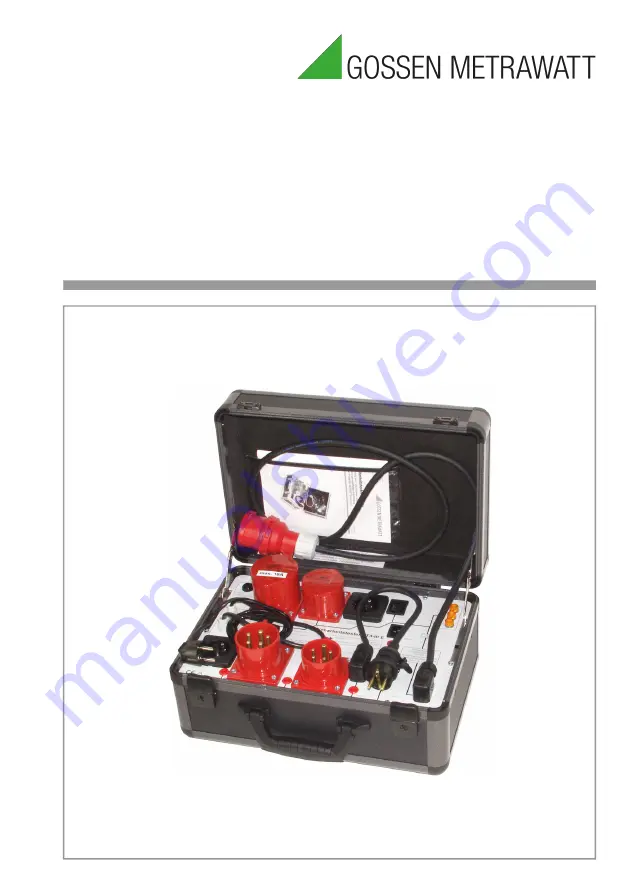
AT3-III E Test Adapter

For the Active and Passive Testing of Single and 3-Phase 

Electric Devices and Extension Cables in Combination 

with SECUTEST.../SECULIFE ST Test Instruments

(M7050…, M7010... and M6930...)

3-349-155-37

17/3.21

Summary of Contents for AT3-III E

Page 1: ...ns AT3 III E Test Adapter For the Active and Passive Testing of Single and 3 Phase Electric Devices and Extension Cables in Combination with SECUTEST SECULIFE ST Test Instruments M7050 M7010 and M6930 3 349 155 37 17 3 21 ...

Page 2: ... Connectors for Test Instruments 12 Earthing contact outlet for power supply to test instru ments 13 Earthing contact plug with cable for insertion into the test socket at the test instrument 14 SECUTEST SIII SIII SIII H SECUTEST S2N S2N 10 N w SECULIFE ST ST HV port for insertion into sockets 2 and 3 at the test instrument SECUTEST PRO ST PRO SECULIFE ST BASE ST BASE25 port and or feature I01 for...

Page 3: ...peri odic testing per DIN VDE 0105 0701 0702 According to these regulations testing must be performed for protective conductor resistance insulation resistance equivalent leakage current residual current and contact current as well as for the absence of voltage depending upon the type of device under test The test adapter in combination with the test instru ment allows for the passive testing of p...

Page 4: ...electrical systems are prohibited The test adapter s 16 A CEE 3P N PE 16 plug may only be connected to 230 400 V 50 Hz mains power In order to avoid unde sired shutdown of defective devices under test the electrical circuit for the device under test should be separately fused Before connecting the AT3 III E to the mains the test instrument must first be connected to the AT3 III E Attention Tests d...

Page 5: ... test probe at the end of the probe cable of the test instrument into the socket 15 at the AT3 III E Connect the test adapter to 230 400 V mains power The test adapter now performs a self test If the tester is intact the red LED lights up briefly 4 Connecting a Device Under Test to the Test Adapter After the device under test has passed a visual inspection and before connecting it to the appro pri...

Page 6: ...ontact current is measured by means of residual current measurement for safety class II devices and safety class I devices with accessible con ductive parts which are not connected to the pro tective conductor Contact all accessible conduc tive parts at the device under test with the test probe at the end of the probe cable form the test instrument to this end These measurements must be performed ...

Page 7: ...erformed due to safety imped ances which have been integrated into the AT3 III E for testing 3 phase devices Figure 1 Connecting Single and 3 Phase Devices to the AT3 III E and the test instrument 230 400 V 50 Hz test adapter AT3 III E L3 L2 L1 SECUTEST 13 230 400 V 50 Hz test adapter AT3 III E L3 L2 L1 SECUTEST 13 COM V 1 SECUTEST SIII SIII SIII H SECUTEST S2N S2N 10 N w SECULIFE ST ST HV SECUTES...

Page 8: ... instrument Observe the following instructions when using the test instrument in combination with the AT3 III E The test probe at the end of the probe cable of the test instrument must first be connected to the respective socket 15 probe 1 to 4 of the associ ated plug at the AT3 III E In order to test only connect the plug and socket at the ends of the respective extension cable to be tested to th...

Page 9: ...e voltage Note When testing device cable connections socket 4 plug 4 polarity L N is not being checked Testing of 3 phase cables is the same except that it also includes an additional test for reversing of conductors L1 L2 L3 and N 3 phase cables have only passed testing for short circuits interruptions and reversed conduc tors clockwise rotation if the following test result appears Cable OK Messa...

Page 10: ... SECUTEST SIII SIII SIII H SECUTEST S2N S2N 10 N w SECULIFE ST ST HV Figure 4 Connecting Single Phase Extension Cables to the AT3 III E and the SECUTEST BASE BASE10 PRO SECUTEST ST BASE ST BASE10 ST PRO SECULIFE ST BASE ST BASE25 SECUTEST 1 2 2 1 230 400 V 50 Hz SECUTEST 3 4 4 4 3 230 V 50 Hz 1 ...

Page 11: ...ntact outlet If an excessively high value or interrup tion is indicated the protective conductor is interrupted The AT3 III E test adapter must be disconnected from the mains and the error in the electrical sys tem or the test adapter must be corrected The AT3 III E is equipped with a Trigger I n test key in order to allow for testing the included I n safety shutdown function at any time Performin...

Page 12: ...ith overload protec tion device In 16 A I2 1 45 In Electrical Safety Pollution degree 2 Safety Class I per DIN EN 61140 VDE 0140 1 Residual Current Shutdown 4 pole at IdN 14 6 mA ta 82 ms Device Fuses F0315 L250V 5 x 20 T32mA L 250 V DIN EN 60127 2 Electromagnetic Compatibility Intrinsic Uncertainty EN 61326 1 2013 class B Intrinsic Uncertainty EN 61326 2013 Mechanical Design Protection case IP40 ...

Page 13: ... make reference to the fact that the current status in this regard can be accessed on the Internet at www gossenmetrawatt com by entering the search term WEEE We identify our electrical and electronic devices in accordance with WEEE 2012 19 EU and ElektroG with the symbol shown to the right per DIN EN 50419 These devices may not be disposed with the trash Please contact our service department rega...

Page 14: ...is available on the Internet All trademarks registered trademarks logos product names and company names are the property of their respective owners Gossen Metrawatt GmbH Südwestpark 15 90449 Nürnberg Germany Phone 49 911 8602 111 Fax 49 911 8602 777 E Mail info gossenmetrawatt com www gossenmetrawatt com ...

Reviews: