

Operators
manual
Gorter-Controls B.V. – Schoonhoven- The Netherlands
Operators manual underground gas pressure reducing station
Type: COCON 26 N-LP
Page 19
4.8 Adjustment data
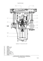
See paragraph 4.7 for the removal of the cartridge from the casing.
When you use several gas pressure reducing stations, we advise you to use a test bench. By using a
test bench, you can adjust spare cartridges before installation.
Ensure that, the minimal differential pressure between the gas in supply and discharge pipes is 0,8
bar.The internal resistance of the cartridge (including a clean dust filter) is 0,8 bar. If the differential
pressure is below 0,8 bar, then the measured reduced pressure will also be lower.
You can adjust the reduced pressure with the regulator pilot. If you set the reduced pressure equal to
100%, then the monitor regulator must start operating at a higher set pressure. The shut-off relay must
close the shut-off valve at a higher pressure then the pressure set by the monitor.
Example:
If you set the pressure to 100 millibar with the regulator pilot, the pressure on the
monitor control pilot must be set at for instance 130 millibar. The shut-off relay
must then be set at for instance 160 millibar.
The adjustments must be readjusted or altered, when parts of the cartridge are replaced or if required
by local conditions. We advise you to work carefully and when necessary, make notes to avoid
unnecessary work and irritation.
Adjustments can be altered per situation or company.
4.8.1 Adjustments
Cartridge adjustments must be carried out in a fixed order. This paragraph describes the proceedings
which have to be carried out, in order to adjust the regulator and monitor control pilots and the
adjustment of the shut-off relay.
You start adjusting after installing the cartridge in the casing (paragraph 4.6.2 on page 16) and after
preforming the leakage test (paragraph 4.6.3 on page 16).
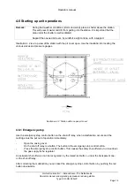
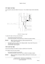
Adjust the regulator, the monitor control and the shut off relay as follows:
-
Loosen the locking nut on the regulator pilot.
-
Turn the spindle on the regulator pilot to the right with a socket head screw spanner, until you
feel some resistance. The regulator is now in a fully open position.
-
Loosen the locking nut on the monitor control pilot
-
Turn the spindle on the monitor control pilot to the left, with a socket head screw spanner.
-
Turn the spindle a little to the right. The monitor control pilot is now set at a low reduced
pressure.
-
Turn the spindle on the shut off relay to the right, with a socket head screw spanner, until you
feel some resistance. The shut off relay now closes the shut off valve, at a high outlet
pressure.
-
Close the butterfly valve DN150 in the discharge pipe, by turning the handle a quarter of a
turn to the left
-
Close the needle valve near the high pressure vent pipe.
-
Open the valve attached in the supply pipe, located within 5 meter of the station.
-
Slowly open the ball valve DN50 in the supply pipe.
The reduced pressure, shown on the pressure gauge, is now controlled by the monitor control.


