PA SERIES PUMPS
MR--04836
MAINTENANCE & REPAIR
PAGE C -- 6
SECTION DRAWING
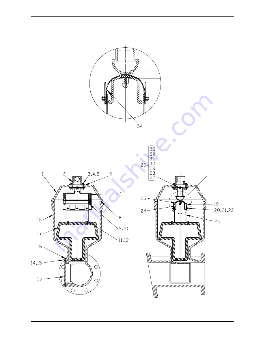
VALVE DETAIL
SEE VALVE DETAIL
Figure C---3. Peeler Type Priming Valve
Page 1: ...4 26 99 Use With OM 04402 THE GORMAN RUPP COMPANY D MANSFIELD OHIO GORMAN RUPP OF CANADA LIMITED D ST THOMAS ONTARIO CANADA Printed in U S A ECopyright by the Gorman Rupp Company PRIME AIREr r r r SER...
Page 2: ...The engine exhaust from this product contains chemicals known to the State of California to cause cancer birth defects or other reproductive harm...
Page 3: ...attention to those which could dam age equipment and to those which could be dan gerous to personnel However this manual cannot possibly anticipate and provide detailed precau tions for every situati...
Page 4: ...nt be abused or modified to change its performance be yond the original factory specifications the war ranty will become void and any claim will be de nied The following are used to alert personnel to...
Page 5: ...nel Before attempting to open or service the pump 1 Familiarize yourself with this man ual 2 Shut down the engine and discon nect the positive battery cable or take other precautions to ensure that th...
Page 6: ...to personnel Use only replacement parts provided or approved by Gorman Rupp Use of non authorized parts may result in damage to the equipment and or injury to personnel and will invalidate the warran...
Page 7: ...ro ken Check and repair replace Eductor safety valve leaking Check and replace safety valve Pump speed too slow Check driver output consult driver operation manual Eductor clogged Check and clean educ...
Page 8: ...e and run engine at maximum governed speed Discharge flow too slow Dilute if possible Suction check valve or foot valve clogged or binding Clean valve Suction intake not submerged at proper level or s...
Page 9: ...ed this section is intended only to provide general recommendations and practices for preventive maintenance Regardless of the application however following a routine pre ventive maintenance schedule...
Page 10: ...r Impeller Clearance Seal Plate I Check Valve I Pressure Relief Valve If So Equipped C Pump and Driver Alignment I Shaft Deflection I Bearings I Bearing Housing I Piping I Driver Lubrication See Mfgr...
Page 11: ...oupled to either a factory supplied or customer supplied en gine Maintenance of engines andfactory supplied air compressors are detailed in separate literature provided by the manufacturer s Check TRO...
Page 12: ...PA SERIES PUMPS MR 04836 MAINTENANCE REPAIR PAGE C 2 SECTION DRAWING C 1 PA6B60 SAE 3 11 5 Pump Assembly...
Page 13: ...e of engines and factory supplied air compressors are detailed in separate literature provided by the manufacturer s MR 04836 PA SERIES PUMPS MAINTENANCE REPAIR PAGE C 3 PA4B60 SAE 3 11 5 Pump Assembl...
Page 14: ...PA SERIES PUMPS MR 04836 MAINTENANCE REPAIR PAGE C 4 SECTION DRAWING Figure C 2 66B60 SAE 3 11 5 Pump Assembly...
Page 15: ...BE FITTING 14 CAP PLUG 15 RETAINING RING 16 RETAINING RING 17 BEARING RETAINER 18 FLEX COUPLING 19 SHAFT KEY 20 IMPELLER SHAFT 21 PILOT BUSHING 22 HEX HD CAPSCREW 23 LOCKWASHER 24 HEX HD CAPSCREW 25 L...
Page 16: ...PA SERIES PUMPS MR 04836 MAINTENANCE REPAIR PAGE C 6 SECTION DRAWING VALVE DETAIL SEE VALVE DETAIL Figure C 3 Peeler Type Priming Valve...
Page 17: ...TUD 6 NECK GASKET 7 VALVE BODY 8 GASKET STRIP 9 STUD 10 HEX LOCK NUT 11 HEX HD CAPSCREW 12 LOCKWASHER 13 INDUCTOR GUARD ASSEMBLY 14 HEX HD CAPSCREW 15 LOCKWASHER 16 GASKET 17 PRIMING VALVE FLOAT 18 PR...
Page 18: ...Clean and reinstall the drain plug This manual will alert personnel to known procedures which require spe cial attention to those which could damage equipment and to those which could be dangerous to...
Page 19: ...33 securing the valve weights 30 and 32 to the check valve Discharge Check Valve Removal and Disassembly Figure C 1 Support the discharge check valve assembly 5 using a sling and a suitable lifting d...
Page 20: ...r the casing feet Tie and tag the shims for ease of reassembly Remove the casing gasket 8 Inspect the balance ring 38 for excessive wear or scoring If replacement is required use a small bit to drill...
Page 21: ...nd inspected in place It is strongly recommended that the bearing be replaced any time the shaft and bearing are removed Clean the intermediate shaft and all component parts except the bearing with a...
Page 22: ...OR ENCLOSED IMPELLERS LOADING DIRECTION OF THRUST BALL LOADING GROOVE POSITIONED AWAY FROM IMPELLER GROOVE DIRECTION OF THRUST LOADING BALL LOADING GROOVE POSITIONED TOWARD IMPELLER GROOVE Figure C 4...
Page 23: ...shaft keyway Posi tion the metal hub portion ofthe couplingassembly 18 onto the shaft to the dimension shown in Fig ure C 2 and secure it by torquing the setscrew to 65 ft lbs 780 in lbs or 9 m kg Mak...
Page 24: ...use an old seal in an emer gency carefully wash all metallic parts in fresh cleaning solvent and allow to dry thoroughly Handle the seal parts with extreme care to prevent damage Be careful not to con...
Page 25: ...diameter as the O D of the seal spring NOTE If the pump casing has not been installed install the casing gasket 8 over the casing studs Position the casing over the shaft and against the intermedi ate...
Page 26: ...til fully seated Make sure the seal spring seats squarely over the step on the back of the impeller Secure the shaft from rotating by reaching through the discharge port and tightly wedging a soft met...
Page 27: ...uds up through the holes in the priming chamber lid and secure with the hardware 3 and 4 Apply Loctite Threadlocker No 242 or equivalent compound to the capscrews 11 Secure the float 17 to the valve s...
Page 28: ...ilure Observe the area between the shaft and bearing retainer 17 as grease is added If old grease is forced out as new grease is added the bearing cavity is full and should be disassembled and cleaned...
Page 29: ...rpumps com warranty or call U S 419 755 1280 International 1 419 755 1352 For Canadian Warranty Information Please Visit www grcanada com warranty or call 519 631 2870 THE GORMAN RUPP COMPANY D MANSFI...