background image

19

MDE-LEDInetworkITS-server-4078V1.3

2.2. CONfIGURaTION DES CaRTES DE SORTIES 

2.2.1. Introduction

votre LEDI Network ITS peut être équipée jusqu’à 3 cartes (4 pour la LEDI Network 

DCLS). Chaque carte de sortie est synchronisée sur le code horaire NTP reçu du ser-

veur NTP ou du GPS ou de la carte d’entrée IRIG B. Chaque carte agit en tant que 

traducteur qui recevant l’heure de la source principale de synchronisation et de la sortie 

spécifique du code horaire.

Actuellement, il y a 9 types de cartes :

NTP/SNTP 

N

 4 sorties AFNOR NFS 87500/IRIGB 1000HZ 

H

4 sorties PPS,PPM, PPH, PP2S, DCF (TTL, differential TTL, 

Phototransistor)

P

4 sorties PPS,PPM, PPH, PP2S, DCF (TTL, differential TTL, 

Static Relay)

Q

4 sorties DCLS (TTL, differential TTL, Phototransistor)

T

4 sorties DCLS (TTL, differential TTL, Static Relay)

v

4 sorties Serial ASCII RS 232 

A

4 sorties Serial ASCII RS 422, RS485 

R

SMPTE

S

2.2.2. Configuration par défaut

Quand vous recevez ce produit de Gorgy Timing, toutes les cartes de sorties sont confi

-

gurées pour fournir l’heure UTC et sans changement d’heure sur l’année.

L’affichage est contrôlé en tant que cartes de sorties et peut être configuré de la même 

manière.

2. 

INSTaLLaTION COMPLETE

Important.

Le format de signal sur des cartes PPS et DCLS peut être changé 

en TTL, différentiel TTL (RS422) ou phototransistor/relais statique 

(dépend du type de carte). Voir l’annexe D - MAINTENANCE 2. Véri-

fication des Switch des cartes de sorties.

FRANCAIS

Summary of Contents for LEDI NETWORK DCLS

Page 1: ...MDE LEDInetworkITS server 4078V1 3 LEDI NETWORK iTS LEDI NETWORK Server MODE D EMPLOI page 3 USER GUIDE page 65 ...

Page 2: ... de l environnement il vous incombe de vous débarrasser de cet équipement dans un site de collecte prévu à cet effet séparément des ordures ménagères Pour de plus amples informations contactez votre revendeur votre site de collecte ou les autorités locales compétentes Toute modification ou ouverture du produit sans l accord du SAV entraîne la perte de la garantie Toute opération de maintenance doi...

Page 3: ...ion réseau 15 2 1 1 Configuration par défaut 15 2 1 2 Changer les paramètres réseaux 16 2 1 3 Intégration à votre réseau 18 2 2 Configuration des cartes de sorties 19 2 2 1 Introduction 19 2 2 2 Configuration par défaut 19 2 2 3 Changer les paramètres 20 2 2 4 Configuration des cartes de sorties du serveur NTP 20 3 Afficheur face avant 21 3 1 Conditions de démarrage 21 3 2 Affichage horaire 22 3 3...

Page 4: ...etManager mais je ne vois aucun produit 46 Je n arrive pas à ouvrir la page WEB de configuration 46 Une ou plusieurs sorties n apparaissent pas dans la page WEB de configuration 47 L écran affiche no time code ou NO TIME CODE 48 Annexe D MAINTENANCE 49 1 Remplacement de la batterie 49 2 Rajout d une carte de sortie 50 3 Vérification des switchs des cartes de sorties 51 3 1 Switchs d adresse 51 3 2...

Page 5: ...tilisant un signal de synchronisation tel que l IRIG B DC l IRIG B AC le NTP le DCF ou par impulsions configurables PPS PPM RS232 RS422 RS485 L utilisation de la LEDI Network ITS de la LEDI Network DCLS ou de la LEDI Network NTP Server vous apportent de nom breux avantages Vous pouvez utiliser l architecture du réseau déjà mis en place avec les protocoles bien connus Ethernet TCP IP Une installati...

Page 6: ...WORK ITS ou DCLS ou NTP SERVER qui est écrit sur la face avant du rack Le code et la configuration du produit peuvent être vérifiés sur l étiquette d iden tification située dessous ou derrière le produit Il doit correspondre à un des numéros suivants 92114 opt ou 92117 opt ou 92100 opt où opt dépend des options du produit Un câble d alimentation uniquement pour les versions 220V AC et 115V AC Un c...

Page 7: ...mande de connaître l adresse physique de chacun des produits Ceci est possible grâce à l outil GTNetMng situé sur le CD ROM Pour plus d information voir la partie 1 2 1 2 Démarrage du produit 1 2 1 Configuration manuelle du réseau Lors de la première installation le produit démarre en mode DHCP Si un serveur DHCP est présent sur le réseau le produit se verra attribuer automa tiquement une adresse ...

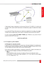
Page 8: ...rité de bon niveau Ce logiciel NTP est étroitement lié à un agent de type SNMP qui permet la gestion et la surveillance du réseau à haut niveau pour les LEDI Network ITS NTP Server 1 3 1 Le protocole NTP NTP Network Time Protocol est un protocole réseau qui permet la synchronisation de différents équipements par un réseau de type TCP IP Ethernet La communication est basée sur un dialogue client se...

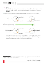
Page 9: ... NTP sur le site www ntp org software 1 3 2 Concept de synchronisation A Principes de correction horaire L objectif de la synchronisation est d avoir deux horloges indiquant la même heure Dans le cas de la synchronisation par NTP l horloge de la LEDI Network ITS NTP Ser ver doit indiquer la même heure que le serveur de temps NTP Pour exécuter cette synchronisation le logiciel de client NTP compare...

Page 10: ...ible la dérive et l offset L exactitude et la stabilité de l horloge du client est étroitement liée à l efficacité du procédé de réduction 2 Il y a plusieurs raisons à la présence d une dérive entre deux horloges généralement la dérive est due à la diffé rence de la température entre les deux horloges Heure serveur Heure client Heure serveur Heure client Heure serveur Heure client Heure serveur He...

Page 11: ... la charge de charge du réseau ou du serveur NTP Le temps de transmission du client au serveur n est géné ralement pas identique à celui du serveur au client En fait sur une grande période la différence de la somme des temps de transmission entre le serveur du client et le client du serveur vaut zéro L algorithme de client NTP mis en application dans la LEDI Network ITS NTP Server est conçu pour c...

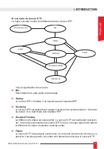
Page 12: ...Apprentissage LelogicieldeclientNTPatrouvéunouplusieursproduitsGorgy Timing auto détection activée oufonctionneaveclesserveursconfigurés Danscetétat lelogicielenregistre les propriétés du réseau Environ 2 minutes sont exigées pour accomplir cette étape Recherche En fonctionnement normal le client NTP évalue de manière permanente son offset et sa dérive avec le serveur Commutation Pas assez de répo...

Page 13: ... tente de se recaler Il ne répond pas aux requêtes NTP Rescaled Tracking La différence de phase est assez petite Le serveur NTP est maintenant opération nel Il répond aux demandes des clients NTP De plus il essaye toujours de réduire la différence de phase si possible tracking mode Failure Le serveur NTP n est pas plus synchronisé et son temps d autonomie est écoulé La précision n est plus garanti...

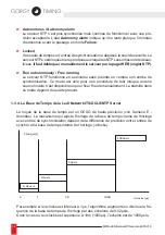
Page 14: ...e mode est utile pour une procédure de test lorsque aucune source horaire n est disponible ou pour fixer l heure manuellement La stabilité dans ce mode dépend du quartz présent 1 3 4 La Base de Temps de la Ledi Network ITS DCLS NTP Server Le noyau de la base de temps est un OCXO de haute précision voir l annexe E données Le mécanisme qui ajuste l horloge de la base de temps inerne de lhorloge avec...

Page 15: ...atiquement l adresse IP d un serveur DHCP Au démarrage le produit envoie une requête DHCP pour obtenir une adresse IP Cette requête contient un nom DHCP Il y a deux cas Si un serveur DHCP est installé sur votre réseau il enregistre la demande DHCP et renvoie une adresse IP La LEDI Network ITS DCLS NTP Server démarre avec cette nouvelle adresse Si aucun serveur DHCP n est installé la LEDI Network I...

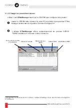
Page 16: ...gramme GTNet Manager localisé dans le répertoire Common Configuration3 L utilitaire GTNetManager affiche automatiquement les produits GORGY TIMING installés sur le réseau comme ci dessous 3 Par exemple si votre lecteur de CD a la lettre E l utilitaire GTNetMng se trouve dans E Common Configuration GTNetMng exe Nom numéro de série et localisation Adresse IP actuelle Masque de sous réseau Identifica...

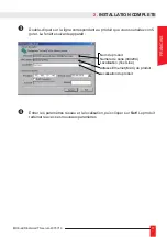
Page 17: ...oduit que vous souhaitez confi gurer La fenêtre suivante apparaît Entrer les paramètres réseau et la localisation puis cliquer sur Set Le produit redémarre avec ses nouveaux paramètres Nom du produit Numéro de série 040204 Localisation Test Line Localisation du produit Adresse Ethernet MAC du produit FRANCAIS ...

Page 18: ...nom inscrit est l identifiant DHCP Puis vous pouvez accéder au produit à partir de votre navigateur WEB ou du navigateur SNMP Par exemple si vous donnez le nom DHCP ntpsrv1 à votre LEDI ITS DCLS NTP Server vous pouvez simplement taper ntpsrv1 dans la zone d adresse de votre navigateur WEB Si vous avez plusieurs produits à installer il est fortement recommandé de suivre les étapes suivantes Utilise...

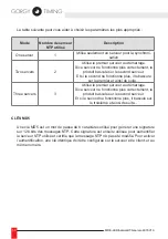
Page 19: ...tor P 4 sorties PPS PPM PPH PP2S DCF TTL differential TTL Static Relay Q 4 sorties DCLS TTL differential TTL Phototransistor T 4 sorties DCLS TTL differential TTL Static Relay V 4 sorties Serial ASCII RS 232 A 4 sorties Serial ASCII RS 422 RS485 R SMPTE S 2 2 2 Configuration par défaut Quand vous recevez ce produit de Gorgy Timing toutes les cartes de sorties sont confi gurées pour fournir l heure...

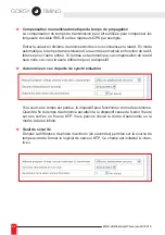
Page 20: ...TP à votre LEDI network ITS DCLS Vous pouvez ainsi synchroniser vos différents réseaux locaux sur plusieurs serveurs NTP eux mêmes synchronisés sur la même source La sortie optionnelle serveur NTP doit être configurée de la même manière que la LEDI Network 1 S RK Enhanced Sa configuration réseau par défaut est le mode DHCP avec l identificateur SCnnnnnn avec nnnnnnn le numéro de série sur 6 chiffr...

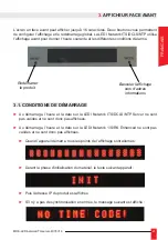
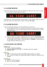
Page 21: ... l heure et la date sur la LEDI Network ITS DCLS NTP Server ne sont pas valides et ne sont donc pas affichées Au démarrage l heure et la date sur la LEDI Network 1 S RK Enhanced ne sont pas valides et ne sont donc pas affichées Quand l appareil démarre tous les points de l affichage sont allumés Durant la phase d initialisation du matériel le texte suivant apparaît Puis l adresse IP du produit est...

Page 22: ...TP Server l heure courante du serveur est affichée en perma nence Lorsque l afficheur est configuré pour donner l heure UTC les informations sui vantes sont affichées par alternance En utilisant le bouton mode vous affichez la précision ou le nombre de satellites GPS détectés IN1 FRI 12 43 13 IN1 07 OCT 2005 07 satellites 20us accuracy 1 us accuracy OCXO LOCK OCXO WARM UP ...

Page 23: ...sion suffisante Le serveur ne délivre plus l heure sur ses sorties ni sur le réseau L afficheur indique L écart de temps en entrée a dépassé le seuil de sécurité security threshold configuré dans la page WEB La LEDI Network se bloque et ne délivre plus l heure sur ses sorties ni sur le réseau L afficheur indique LOCKED Il faut accéder à la page WEB pour débloquer le serveur 3 5 Face avant NTP Serv...

Page 24: ...WEB qui délivre une page WEB Ce site WEB est une applet JAVA Si besoin vous trouverez une JVM Java Virtual Machine sur le CD ROM dans le répertoire Common JAVA Pour accéder au site WEB entrer l adresse de la LEDI Network ITS DCLS NTP dans le champ d adresses de votre navigateur WEB comme ci dessous et appuyer sur Entrée 4 4 Si vous avez configuré votre LEDI NETWORK ENHANCED en mode DHCP et que vot...

Page 25: ...n du serveur NTP Input Configuration du décalage par rapport à l entrée de synchronisation Ré glage de l autonomie passage en mode autonome Free running Output configuration des sorties et de l affichage Download charger un nouveau programme Le bouton Submit sauvegarde immédiatement la configuration de la LEDI Network ITS DCLS NTP avec les nouveaux paramètres Ces paramètres sont alors stockés en p...

Page 26: ...guré en mode DHCP Il est composé d au maximum 8 lettres Network submask Indique la taille du réseau que vous utilisez Par exemple un masque se sous réseau de 255 255 255 0 indique que seul le dernier numéro de l IP change dans l exemple ci dessus l adresse dans le réseau peut varier entre 192 168 10 1 à 192 168 10 254 5 Gateway address Si vous voulez que le produit communique avec d autres apparei...

Page 27: ...e l interface Ethernet du produit Firmware Version Release Date Version du logiciel fonctionnant sur le produit et la date du dernier logiciel produit au format anglais yymmdd par exemple 021010 pour le 10 Octobre 2002 Last reboot reason Indication sur la raison du dernier redémarrage du produit Protection de l accès au site WEB Si vous souhaitez protéger l accès aux paramètres du produit vous pou...

Page 28: ...ients NTP Reference ID 4 lettres qui donnent l information sur la référence de temps Cette info est ajoutée à la trame NTP When not synchronized Définit certains champs inclus dans la trame NTP quand le produit n est plus syn chronisé Choix possible entre LI STRATUM unchanged STRATUM 0 LI un changed STRATUM unchanged LI 3 11b STRATUM 0 LI 3 11b La LEDI Network ITS peut être synchronisée avec au pl...

Page 29: ...02 D autre part la partie d écran ci dessous montre quel est le serveur actuellement utilisé pour la synchronisation avec une trame intitulée Active La partie du milieu l écran NTP vous permet de configurer le mode de synchronisation et les serveurs NTP utilisés Si vous choisissez l Auto détection dans le menu déroulant la LEDI Network ITS DCLS NTP essaie d utiliser les serveurs présents sur votre...

Page 30: ...ur le premier et ainsi de suite Three servers 3 Utilise le premier serveur au démarrage Si ce serveur ne fonctionne plus correctement le produit bascule sur le second serveur Et si le second ne fonctionne plus il bascule sur le troisième et ainsi de suite Clés MD5 Une clé MD5 est un mot de passe de 8 caractères utilisé pour générer une signature sur 128 bits des messages NTP Cette signature est en...

Page 31: ...quant sur Submit Remarque ce mode est utile en phase de test si aucune source de synchronisation n est disponible Sinon la date n est pas exacte et la précision n est plus garantie B Entrée 1 ou Entrée 2 Heure locale sur l entrée Dans la plupart des cas le produit est synchronisé avec un code horaire décalé par rapport à l UTC par exemple TDF DCF il faut donc configurer le réseau horaire et la pol...

Page 32: ...autre entrée Si l entrée est automatique sa compensation du retard sera nulle car c est la seule référence pour le dispositif Autonomie en cas de perte de synchronisation Si la source de temps est perdue le dispositif peut fonctionner en mode autonome Quand la fin du temps d autonomie est atteinte le dispositif cesse de fournir l heure sur ses sorties ou l heure NTP Vous pouvez choisir la durée d ...

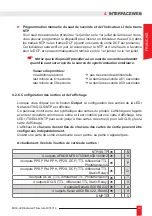
Page 33: ...figuration des sorties et de l affichage Lorsque vous cliquez sur le bouton Output la configuration des sorties de la LEDI Network ITS DCLS NTP est affichée Ce panneau montre une vue synthétique des sorties du produit L affichage en façade avant est considéré comme une sortie et il est contrôlé par une carte d affichage Une LEDI ITS DCLS NTP peut avoir jusqu à trois cartes de sortie 4 pour la DCLS...

Page 34: ... Pour les sorties AFNOR la porteuse n est plus modulée La sortie ALARM ne génère pas de signal d alarme Zone horaire La Time Zone zone horaire est un offset d heure qui peut être ajouté ou sous trait à l heure reçue depuis le protocole NTP qui donne l heure UTC pour générer l heure locale Par exemple pour la France l heure locale est fixée à GMT 1 00 Changement d heure En plus de la zone horaire d...

Page 35: ...ut le dernier samedi d octobre Fin le dernier samedi de mars Russie Début le dernier samedi de mars à 2 heures du matin Fin Le dernier samedi d octobre à 2 heures du matin Configuration pour affiner les sorties La plupart des cartes de sortie fournissent une configuration spécifique Configuration ASCII PPS Vous pouvez configurer ici la largeur et la période du TOP Comme par exemple le TOP DCF PPS ...

Page 36: ...du code de la sortie SMPTE peut être configuré ici Le champ de bit utili sateur peut être automatiquement défini avec la date ou rempli manuellement L heure du code SMPTE peut être recalée chaque seconde sur la base de temps du produit ou à une heure spécifique du jour ...

Page 37: ...esse s IP pour l envoi des alertes traps Nom du produit informatif Emplacement du produit informatif Contact pour le produit informatif Les alertes générées tout comme la MIB sont au format V2c Pour plus d informations sur les alertes et la MIB se reporter au document référence R2 028 3F 487A présent sur le CDRom sous le nom F487A Manuel SNMP V2c de la gamme ITS pdf 4 Interface WEB FRANCAIS ...

Page 38: ...uit 1 Connexion pour touS les produits 2 Sorties 1PPS et 10MHz Connecteur 1PPS C nnecteur 10 MHz seulement avec OCXO Annexe A Connexions 18 72VDC 230 VDC Etat sortie usine Reset Antenne GPS connecteur SMA avec adaptateur TNC Sortie TTL 10 Mhz Sinusoïde 10 Mhz output Relais statiques alarmes tension et synchro Deuxième entrée de synchronisation GND 10Mz sinusoïdale GND Format 1PPS TTL ...

Page 39: ...ais statiques 5 ENTRÉE AFNOR NFS87500 IRIG B sinusoïdale TTL RS422 L entrée de synchronisation AFNOR IRIG B est une prise 2 points non polarisée en modu lé et polarisée en TTL RS422 Annexe A Connexions 12 34 Pins 3 alarme alimentation sans polarité Pins 1 2 alarme synchronisation sans polarité 18 72 VDC FRANCAIS ...

Page 40: ...teur DB9 permet de sortir 4 lignes ASCII indépendantes RS232 RS485 RS422 1 TX4 TX4 2 GND TX1 3 TX1 TX1 4 GND TX4 5 GND TX3 6 TX3 TX3 7 TX2 TX2 8 GND TX2 9 N C N C 8 Sorties SMPTE Connecteur SMPTE Connecteur Blackburst Sortie 1Sortie 2Sortie 3Sortie 4 Sortie 1 Sortie 2 Sortie 3 Sortie 4 Blackburst GND 1 GND 2 Chaud 3 Froid ...

Page 41: ...n octet simple dont la valeur est 2 marque le commencement de la trame DAY 3 Le jour de la semaine est en anglais MON pour Monday lundi TUE pour Tuesday Mardi WED pour Wednesday THU pour Thursday FRI pour Friday SAT pour Saturday SUN pour Sunday DD 2 Le jour du mois sur 2 caractères ASCII 01 31 MM 2 Le mois de l année sur 2 caractères ASCII 01 12 YY 2 L année sur 2 caractères ASCII 00 pour 2000 99...

Page 42: ...42 MDE LEDInetworkITS server 4078V1 3 2 AFNOR IRIG B NFS87500 2 1 Format de la trame ...

Page 43: ...43 MDE LEDInetworkITS server 4078V1 3 Annexe B Format du code de sortie 2 2 Encodage des bits Le signal est modulé seulement sur la carte B Le signal de sortie de la carte T est un signal TTL FRANCAIS ...

Page 44: ... H Indique un changement d heure saisonnier à l heure suivante HE Heure d été HH Heure d hiver P1 P2 P3 Bits de parité 0 10 20 30 40 50 bits de contrôle minutes heures quantiemes jour dans le mois jour de la semaine 1 lundi 7 dimanche mois année bits 0 de synchro 2 4 10 20 40 80 P1 P2 P3 M 20 20 20 40 10 10 10 8 8 8 8 8 4 4 4 4 4 2 2 2 2 2 1 1 1 1 1 10 0 1 J 1 JF JF ES HE E H HH 1 urs re er au eme...

Page 45: ...4 th BINARY GROUP BI PHASE MARK PHASE CORRECTION BIT EBU SECONDS TENS 3 d BINARY GROUP SECONDS UNITS 2 d BINARY GROUP COLOR FRAME FLAG FRAMES TENS 1 st d BINARY GROUP FRAMES UNITS START CLOCK EDGE BETWEEN BIT 79 AND BIT 0 80 BITS PER FRAME 32 USER BINARY SPARE BITS 16 SYNC 31 ASSIGNED ADDRESS 1 UNASSIGNED ADDRESS THE UNASSIGNED BIT IS LOGICAL ZERO UNTIL ASSIGNED RECORDED WAVEFORM CLOCK 1 0 1 1 0 1...

Page 46: ...z plusieurs VLAN Réseau local virtuel vérifiez que le produit est bien sur le même VLAN que votre ordinateur Connectez votre ordinateur directement au produit en utilisant un câble croisé En mode DHCP le produit prend automatiquement une adresse IP dans la gamme 169 254 x y s il n y a pas de serveur DHCP Changez l adresse IP de votre ordina teur dans cette gamme avec un masque réseau de 255 255 0 ...

Page 47: ...ctionner Factory default puis Quit save Rafraichir la page Si ça ne change rien passer à la suite Une ou plusieurs sorties n apparaissent pas dans la page WEB de configuration Appuyer sur F5 pour rafraîchir la page WEB puis retourner dans l onglet output Si la sortie n apparait toujours pas passer à l étape suivante Ouvrir une session TELNET dans une fenêtre de commande telnet adresse_ip_du_produi...

Page 48: ...de ou no time code NO TIME CODE vérifier la source de synchronisation externe car le produit n est pas synchronisé no time code avec la date si le produit reçoit le code horaire aller dans l onglet input de la page WEB et vérifier que run autonomous n est pas coché ...

Page 49: ... et laisser la batterie se charger au moins une heure Déconnecter le produit de l alimentation Ouvrer le produit à l aide d un tournevis La batterie se situe entre la carte alimen tation et l afficheur Retirer l ancienne batterie à l aide d un tournevis Contrôler la tension aux bornes de la batterie si elle est inférieure à 7Volts la bat terie est hors d usage Brancher une nouvelle batterie Displa...

Page 50: ...tirant les vis une vis centrale ou 16 vis latérales Débrancher le connecteur de la batterie la carte GPS ou NTP doit s éteindre La nouvelle carte à installer comporte les accessoires suivant Vis M3 Entretoises Cache pour façade arrière Procédure de montage 1 Monter les entretoises et vis sur le fond 2 Visser le cache sur la façade arrière ...

Page 51: ...pparaît pas dans la page WEB ouvrez le produit et vérifiez la configu ration des switchs sur les cartes Sortie 1 la plus proche de la carte ali mentation Sortie 2 Sortie 3 Sortie 4 la plus éloignée de la carte ali mentation 1 sortie 1 2 3 4 5 6 7 8 2 sorties 1 2 3 4 5 6 7 8 1 2 3 4 5 6 7 8 3 sorties 1 2 3 4 5 6 7 8 1 2 3 4 5 6 7 8 1 2 3 4 5 6 7 8 4 sorties 1 2 3 4 5 6 7 8 1 2 3 4 5 6 7 8 1 2 3 4 5...

Page 52: ...formats de signal TTL TTL Différentiel RS422 Phototransistors ou relais statiques dépend du type de carte Format du signal Pour chaque sortie Switch 1 Switch 2 Switch 3 Phototransistor ou relais statique ON à droite ON à droite ON à droite RS422 Différentiel TTL ON à droite OFF à gauche OFF à gauche TTL OFF à gauche OFF à gauche OFF à gauche SW1 SW2 SW3 SW1 SW2 SW3 Sortie 4 Sortie 3 OFF ON ...

Page 53: ...ur la carte principale 4 1 Switchs de la carte principale de la LEDI Network DCLS Type de code horaire Code d entrée Entrée 1 Switch 1 Switch 2 IEEE1344 OFF à gauche OFF à gauche IEEE1344 ON à droite OFF à gauche IRIG B OFF à gauche ON Right AFNOR ON à droite ON à droite Code d entrée Entrée 2 Switch 3 Switch 4 IEEE1344 OFF à gauche OFF à gauche IEEE1344 ON à droite OFF à gauche IRIG B OFF à gauch...

Page 54: ...à droite ON à droite OFF à gauche RS422 OFF à gauche ON à droite ON à droite OFF à gauche ON à droite ON à droite RS422 avec une charge de 120 Ohms OFF à gauche OFF à gauche ON à droite OFF à gauche OFF à gauche ON à droite Format DCLS Entrée 1 Entrée 2 SW 16 SW 9 Non inversé ON à droite ON à droite Inversé OFF à gauche OFF à gauche SW10 SW15 SW16 SW9 SW11 SW12 SW13 SW14 OFF ON ...

Page 55: ... OFF ON ON OUI NTP X X OFF NON None X X ON NON Carte option d entrée AFNOR IRIG B Switchs DCLS TTL DCLS RS422 differentiel TTL Signal modulé 1 ON à droite OFF à gauche OFF à gauche 2 ON à droite ON à droite OFF à gauche 3 ON à droite ON à droite OFF à gauche 4 ON à droite ON à droite OFF à gauche 5 ON à droite OFF à gauche OFF à gauche 6 Charge ON OFF OFF à gauche Gauche Droite OFF à gauche 7 Inve...

Page 56: ...56 MDE LEDInetworkITS server 4078V1 3 1 Dimensions Le rack est au format standard 19 1U rack Voici ses dimensions Annexe E Caractéristiques 1U 44 mm 424 mm 263 mm 482 mm ...

Page 57: ...le 18 72V DC Environnement Température de fonctionnement 5 to 50 C 41 to 122 F Température de stockage 40 to 70 C 40 to 151 F Autonomie électrique 1 heure sur les batteries interne NiMH 5 à 7 ans de durée de vie Dimensions 44mm 1U x 263mm x 482mm 19 Poids 2 3 Kg Certifications CE EN 60950 EN 55022 EN 50024 Stabilité Fréquence 5 10 10 Précision 10 9 OCXO Stabilité de la Fréquence de 0 C à 60 C 1 10...

Page 58: ...nts DCLS TTL RS422 DB9 Ethernet 10 100BaseT RJ45 Antenne GPS Dimensions 3 05 D x 2 61 H 775mm x 662mm Température de fonctionnement 40 C to 85 C Câble RG59 25m 60m 80m Carte d entrée du niveau minimum du GPS dB 18 dB Sorties standards Signal Connecteur 10 MHz sinusoïdale BNC 10 MHz carré BNC SNMP HTTP Ethernet 10 100BaseT RJ45 Deux relais statiques d alarmes Tension d alimentation Synchronisation ...

Page 59: ...TTL ou Top configu rable PPS DCF Relais statique 350 V AC DC 130 mA TTL temps de montée 10ns différentiel TTL temps de montée 10ns 8 pins conn 500µs 100ns 100ns SMPTE 2 pins conn Protocoles réseau Network Time Protocol NTP NTP v2 RFC 1305 NTP v3 RFC 1305 NTP v4 SNTP RFC 2030 UDP TCP Time Protocol RFC 868 SNMP v1 RFC 1157 MIB II RFC 1213 DHCP RFC 2131 HTTP HTML RFC 2616 TELNET RFC 854 à 861 Configu...

Page 60: ...TENSION DES SORTIES 3 maximum U NTP SNTP N 4 sorties AFNOR NFS 87500 IRIGB 1000HZ H 4 sorties PPS PPM PPH PP2S DCF TTL différentiel TTL Phototransistor P 4 sorties PPS PPM PPH PP2S DCF TTL différentiel TTL Relais statique Q 4 sorties DCLS TTL différentiel TTL Phototransistor T 4 sorties DCLS TTL différentiel TTL Relais statique V 4 sorties série ASCII RS 232 A 4 sorties série ASCII RS 422 RS485 R ...

Page 61: ...8V1 3 4 Etiquette code produit L étiquette qui identifie le produit se situe sur le dessus ou la face arrière du produit Elle contient les informations suivantes Annexe E Caractéristiques GORGY TIMING CODE optX N SERIE nnnnnn FRANCAIS ...

Page 62: ...ibuer Description de l installation vous pouvez utiliser cette table pour créer une vue synthétique de toute votre installation Configuration de l appareil vous pouvez utiliser cette table pour enregistrer la configuration des sorties et afficheur de chaque produit Vue résumée de l installation Description de l installation Date d installation Nom de l installateur Description du produit Numéro de...

Page 63: ...63 MDE LEDInetworkITS server 4078V1 3 NOTES FRANCAIS ...

Page 64: ...82 38 04877 38 GORGY TIMING RC 74 B 38 Toutes modifications d ordre technique ou esthétique peuvent être apportées sans préavis support gorgy timing fr SUPPORT TECHNIQUE depuis la France sur un poste fixe GORGY TIMING SAS Quartier Beauregard 38350 La Mure d Isère Grenoble France Phone 33 4 76 30 48 20 Fax 33 4 76 30 85 33 email gorgy gorgy timing fr www gorgy timing com ...

Page 65: ...65 MDE LEDInetworkITS server 4078V1 3 USER GUIDE LEDI Network its LEDI Network server ENGLISH ...

Page 66: ... protection of persons and the environment you must dispose of this equipment in a collection site provided for this purpose separately from household waste Contact your reseller collec tion site or the competent lcoal authorities for more information Modifying or opening the product without the consent of the Customer service department will void the warranty All maintenance operation shall be co...

Page 67: ...UP 79 2 1 Network configuration 79 2 1 1 Default configuration 79 2 1 2 Changing network parameters 80 2 1 3 Integration in your network 82 2 2 Output cards configuration 83 2 2 1 Introduction 83 2 2 2 Default configuration 83 2 2 3 Change the settings 84 2 2 4 NTP server output card configuration 84 3 Front display interface 85 3 1 Start up conditions 85 3 2 Time display 86 3 3 Minor alarm condit...

Page 68: ...nager but I cannot see the device 110 I cannot open the configuration WEB page 110 An output is not visible in the configuration WEB page 111 The screen displays no time code or NO TIME CODE 111 Appendix D MAINTENANCE 112 1 Procedure to follow to change the battery 112 2 Addition of an output card 113 3 Output card switches verification 114 3 1 Address switches 114 3 2 Output signal format modific...

Page 69: ...r several product using a synchro nization signal such as IRIG B DC IRIG B AC NTP DCF or configurable Pulse PPS PPM RS232 RS422 RS485 Using the LEDI Network ITS LEDI Network DCLS and LEDI Network NTP Server provides you with several advantages You can use the installed network architecture with the well known protocols Ethernet TCP IP Simplified set up Easy remote configuration and diagnostic The ...

Page 70: ...e name of this product is LEDI NETWORK ITS or DCLS or NTP SERVER which is written on the front side of the rack The code and configuration of the product can be checked on the identification stamp put on top or backside of the product It must be 92114 opt or 92117 opt or 92100 opt where opt depends on the product options A power supply cable only for 220V AC and 115V AC versions A 3 pins connector...

Page 71: ...ation Gorgy Timing NTP products are configured in factory to automatically get an IP ad dress Two mechanisms are used If a DHCP server is present on your network our products get an address automa tically This ensures that the IP address is compatible with your network If no DHCP server is present the product automatically takes an IP address using the AutoIP mechanism In this case the address is ...

Page 72: ...y This NTP software is tightly coupled to a SNMP agent that allows high level management and supervision of the LEDI Network ITS NTP Server 1 3 1 The NTP protocol NTP Network Time Protocol is a network protocol that allows the time synchronisa tion of different equipments through a TCP IP Ethernet network The communication is based on a client server dialog The LEDI Network ITS acts as the server ...

Page 73: ...hardware on the site www ntp org software 1 3 2 Synchronization concepts A Clock Correction principles The objective of the synchronization is to make two clocks indicating the same time In the case of NTP based synchronization the LEDI Network ITS NTP Server clock must indicate the same time that the NTP server clock To perform this synchronization the NTP client software permanently compares the...

Page 74: ...NTP server is to reduce as much as possible the drift and the offset The accuracy and stability of the client clock is tightly coupled to the efficiency of the reduction process 3 There are several reasons for the presence of a drift between two clocks generally the drift is due to the tempera ture difference between the two clocks Heure serveur Heure client Heure serveur Heure client Dérive const...

Page 75: ...n vary because of network load or NTP server load Worse the transmission time from client to server is generally not the same that the one from the server to client Actually on a large period of time the difference of sum of client server and server client transmission delays is zero The NTP client algorithm implemented in the LEDI Network ITS NTP Server is designed to compensate transmission dela...

Page 76: ...rver is required to leave this state Learning The NTP client software has found one or several Gorgy Timing auto detection ac tivated or works with configured servers In this state the software learns network properties About 2 minutes are required to complete this stage Tracking Normal behavior the NTP client permanently evaluate its offset and drift with the server Commuting Not enough reply rec...

Page 77: ...ng The NTP software has received both the date and the PPS from the hardware The phase difference is too important The NTP software doesn t reply to NTP clients requests and try to reduce the phase difference Rescaled Tracking The phase difference is small enough The NTP server is now operational It replies to NTP clients requests Moreover it still try to reduce the phase difference if pos sible t...

Page 78: ... the date becomes lower than the threshold value again or until a reboot Run autonomously Free Running The NTP server run without using the time source code This mode is useful for test procedure when no time source is available but the time stability is dependant of the quartz present on hardware 1 3 4 The Ledi Network ITS DCLS NTP Server Time Base The core of the time base is an high accurate OC...

Page 79: ...to get an IP address This query contains a DHCP name There are two cases If a DHCP server is installed on the network it record the DHCP name and return an IP address The LEDI Network ITS DCLS NTP Server starts working with this address If no DHCP server is installed the LEDI Network ITS DCLS NTP Server automati cally uses a default IP address in the range 169 254 x y where x and y are between 0 a...

Page 80: ...n the directory Common Configuration4 The GTNetMng tool displays automatically the Gorgy Timing products installed on your network Each line contains information about one connected product as shown below 4 For example if your CD reader has letter E the GTNetMng tool is localized in E Common Configuration GTNetMng exe Name serial number and localization Current IP address network mask DHCP identif...

Page 81: ...e related to the product you want to configure The fol lowing panel is displayed Set the network parameters and physical localization and click the Set button Name of the device Serial number Localization Ethernet MAC address of the device Localization of the product ENGLISH ...

Page 82: ... is the DHCP identifier Then you can access to the device from your WEB or SNMP browser For example if you give the DHCP name ntpsrv1 to your LEDI Network ITS DCLS NTP Server you can simply type ntpsrv1 in the address field of your WEB browser If you have several products to install on your installation it is highly recommended to follow the following steps Use the document provided in Appendix F ...

Page 83: ...ransistor P 4 sorties PPS PPM PPH PP2S DCF TTL differential TTL Static Relay Q 4 sorties DCLS TTL differential TTL Phototransistor T 4 sorties DCLS TTL differential TTL Static Relay V 4 sorties Serial ASCII RS 232 A 4 sorties Serial ASCII RS 422 RS485 R SMPTE S 2 2 2 Default configuration When you receive this product from Gorgy Timing all the output cards are configured to output UTC time and tim...

Page 84: ...ay you can synchronize your different local networks on several NTP servers synchroni zing themselves on the same hardware reference The NTP server card has to be configured by the same way than the LEDI Network ITS DCLS Its default network configuration is DHCP mode with identifier SCnnnnnn with nnnnnn the serial number on 6 digits The default SNMP name of the NTP server that can be seen from a S...

Page 85: ...en Front Panel Display Mode 3 1 Start up conditions During start up the time and date of the LEDI Network ITS DCLS NTP Server are not valid and are not displayed Then you can see the following texts When the device start all the dots of the displays are lightened During hardware initialization the following text is displayed Then the IP address of the product appears If there is no time code at th...

Page 86: ...P Server the current time of the server is permanently displayed When display is configured to show UTC time the following information are alter natively displayed By Using the mode button you display either the accuracy or the number of GPS satellites IN1 FRI 12 43 13 IN1 07 OCT 2005 07 satellites 20us accuracy 1 us accuracy OCXO LOCK OCXO WARM UP ...

Page 87: ...y to rescale its clock and display Rescaling 3 4 Major alarm conditions There are two different alarms Without time code and when the LEDI Network ITS DCLS NTP Server can t guaran tee accuracy it stops deliver time on outputs or NTP and displays the following text 3 5 NTP Server front display POWER GREEN Main power supply is OK Flash every second running on battery OFF OFF SYNC GREEN The product i...

Page 88: ...rver software itself Management and diagnostic of output cards Each LEDI Network ITS DCLS NTP Server has its own WEB server that delivers WEB pages To access the WEB site type in the address of the device in the address field of your WEB browser as shown below and validate the input 5 5 If you have configured your LEDI Network ITS DCLS NTP Server in DHCP mode and that your server automati cally re...

Page 89: ...stic and configuration of the NTP software behavior Input offset from input time code autonomy and autonomous running mode confi guration Output diagnostic and configuration of output cards and display Download Download a new software release The Submit button updates immediately the LEDI Network ITS DCLS NTP Server configuration The configuration is stored permanently in an EEPROM 4 WEB Interface...

Page 90: ...o be used when the device is configured in DHCP mode This identifier has 8 letters maximum Network submask Indicate the width of the network you use For example a network submask 255 255 255 0 indicates that only the last number change in the example above address in the network can change between 192 168 10 1 to 192 168 10 254 6 Gateway address If you want the device to communicate with devices o...

Page 91: ...Firmware Version Release Date Version of the software running in the clock and date of the last produced software in English format yymmdd for example 021010 for 2002 October the 10th Last reboot reason A text that Indicates why the device has restarted the last time WEB site access protection If you want to protect access to the parameters of the device you can specify a pas sword This is done by...

Page 92: ...fe rence This value is put in the appropriate field in the NTP frame When not synchronized Define the effect on some NTP fields when the device is not synchronized7 The possible values are LI STRATUM unchanged STRATUM 0 LI unchanged STRATUM unchanged LI 3 11b STRATUM 0 LI 3 11b The LEDI Network ITS can be synchronized on up to three NTP servers In fact the NTP software uses only one server at the ...

Page 93: ...urrently used for synchronization with a frame labeled Active If a commutation is in progress the label Trying is dis played nears the related NTP server The middle part of the NTP screen allows you to configure the synchronization mode and the NTP servers used If you select the checkbox Auto detection the LEDI Network ITS try to use the NTP servers present on your network and use the more appropr...

Page 94: ... server 1 Use only one server for synchronization Two servers 2 Use the first server at startup If this server fails commute to the second server If this server fails commute to the first one and so on Three servers 3 Use the first server at startup If this server fails commute to the second server If this server fails commute to the third one and so on ...

Page 95: ...ent server synchronization tests or if you don t have a synchronization source However the date is not exact and the accuracy is not guaranteed B Input 1 or Input 2 Local Time on input In some cases the device is not synchronized on an UTC time source but on a local time source for example Then you need to configure the time zone from the Greenwich Mean Time GMT and the Day Saving Time policy of t...

Page 96: ... from the driving input If the driving input is in automatic its compensation delay will be null as it is the reference for the device Autonomy If the time source is lost the device can work in autonomous mode When the auto nomy time end is reached the device stops to provide time on his outputs or NTP time You can choose the autonomous duration or set it to infinite duration Security threshold Gi...

Page 97: ...ck on the Output button the configuration of the output of the LEDI Network ITS DCLS is displayed This panel shows a synthetic view of the outputs of the product The display is conside red as an output and is driven by a display card A LEDI Network ITS can contain up to 3 output cards 4 for the DCLS plus the display card The display and each output of each output cards can be configured INDEPEN DE...

Page 98: ... are in the open state For AFNOR output the carrier is not modulated The ALARM output doesn t generate warning signal Time Zone The Time Zone is a time offset that can be added or subtracted from the time received through the NTP protocol which is UTC time to ge nerate local time For example in France local time is GMT 1 00 Day Saving Time In addition to the Time Zone many countries apply a Day Sa...

Page 99: ...unday in October Australia Standard Start Last Sunday in October End Last Sunday in March Russia Start Last Sunday in March at 2 am local time End Last Sunday in October at 2 am local time Fine output configuration Some output cards provide specific configuration ASCII PPS configuration You can configure here the period and the width of the TOP For example DCF top PPS PPM AFNOR IRIG B configuratio...

Page 100: ...figuration The SMPTE output code format can be configured here The user bit field ban be customized or automatically filled with the date The time of the SMPTE code can be rescaled every second on the device time base or at a specific time of the day ...

Page 101: ...o configure the main elements of such alerts IP address es for sending alerts traps Product Name for information System location for information System contact for information The generated alerts traps and the MIB are in v2c format For more information on traps and MIB please view the document available on the CDRom at the A487A SNMP V2c ITS Range manual pdf reference ENGLISH ...

Page 102: ...ized on the backside of the product 1 Connection for all products 2 1PPS and 10MHz outputs 1PPS connector 10MHz connector only for OCXO Appendix A Connections 18 72VDC 230 VDC Factory Default Reset GPS antenna SMA connector TTL 1MHz output Wave 10 Mhz output Dry contact output Power and Sync Alarm Second synchronization input GND 10Mz sinusoïdale GND Format 1PPS TTL ...

Page 103: ... 4 Alarm 5 AFNOR NFS87500 IRIG B input sine wave TTL RS422 The AFNOR IRIG B synchronization input is localized on the backside of the device Synchronization is done through a 2 points plug without polarity as shown below 18 72 VDC 12 34 Pin 3 4 Power alarm without polarity Pin 1 2 Synchronization alarm without polarity ENGLISH ...

Page 104: ...ne wave 7 ASCII output 4 outputs on DB9 connector RS232 RS485 RS422 1 TX4 TX4 2 GND TX1 3 TX1 TX1 4 GND TX4 5 GND TX3 6 TX3 TX3 7 TX2 TX2 8 GND TX2 9 N C N C 8 SMPTE OUTPUT SMPTE connector Blackburst connector Output 1 Output 2 Output 3 Output 4 1 GND 2 Hot 3 Cold Blackburst GND ...

Page 105: ...ing STX 1 A single byte which value is 2 mark the beginning of the frame DAY 3 The day in the week in a human readable way MON for Monday TUE for Tuesday WED for Wednesday THU for Thursday FRI for Friday SAT for Saturday SUN for Sunday DD 2 Day in the month on two characters ASCII 01 31 MM 2 Month in the year on two characters ASCII 01 12 YY 2 Year on two characters ASCII 00 for 2000 99 for 2099 H...

Page 106: ...106 MDE LEDInetworkITS server 4078V1 3 2 AFNOR IRIG B NFS87500 2 1 Frame format ...

Page 107: ...107 MDE LEDInetworkITS server 4078V1 3 Appendix B Output code format 2 2 Bit encoding The signal is modulated only on B card The T card output signal has TTL level ENGLISH ...

Page 108: ...andby transmitter used E H Indicates a seasonal changeover on the next hour HE Summer time HH Winter time P1 P2 P3 Parity bits 0 10 20 30 40 50 minutes 2 4 10 20 40 80 P1 P2 P3 M 20 20 20 40 10 10 10 8 8 8 8 8 4 4 4 4 4 2 2 2 2 2 1 1 1 1 1 10 0 1 J 1 JF JF ES HE E H HH 1 0 synchronization bits control bits hours day of month day of week 1 monday 7 sunday month year ...

Page 109: ... th BINARY GROUP MINUTES UNITS 4 th BINARY GROUP BI PHASE MARK PHASE CORRECTION BIT EBU SECONDS TENS 3 d BINARY GROUP SECONDS UNITS 2 d BINARY GROUP COLOR FRAME FLAG FRAMES TENS 1 st d BINARY GROUP FRAMES UNITS START CLOCK EDGE BETWEEN BIT 79 AND BIT 0 80 BITS PER FRAME 32 USER BINARY SPARE BITS 16 SYNC 31 ASSIGNED ADDRESS 1 UNASSIGNED ADDRESS THE UNASSIGNED BIT IS LOGICAL ZERO UNTIL ASSIGNED RECO...

Page 110: ...VLAN than your computer Connect your computer directly to the device using a straight cable In DHCP mode the device take automatically an address in the ran ge 169 254 x y if it does not find any DHCP server Change your com puter IP address in this range with a network mask of 255 255 0 0 I cannot open the configuration WEB page First is the device reachable with GTNetManager YES Your computer and...

Page 111: ...int Open a TELNET session Telnet ip address 10000 Password gtmt Proceed to a Factory Default then Quit and save Refresh the WEB page If the output is still missing open the device Check the black cables connections and the switches configurations see Appendix D MAINTENANCE Output card switches verification The screen displays no time code or NO TIME CODE NO TIME CODE verify your time source becaus...

Page 112: ...duct to the 230VAC during one hour Remove the power supply Open the product with the screw driver the battery is located between the power supply card and the display card Disconnect the old battery with the screw driver Check the voltage if the voltage is less than 7V the battery is on failure Connect the new battery with the screw driver Display Output 1 Output 2 Output N Batterie Entrée Sync Po...

Page 113: ...oving screws one central screw or 16 lateral screws Disconnect the battery connector the GPS card or NTP should go out The new card to install has the following accessories M3 Screw Spacers A cover for the back face Mounting procedure 1 Fit the spacers and screws on the bottom face 2 Screw the cover on the back face ENGLISH ...

Page 114: ...o be in failure do not appear in the WEB page open the device and verify the switch configuration on the output cards Output 1 the nearest of the supply card Output 2 Output 3 Output 4 the furthest of the supply card 1 sortie 1 2 3 4 5 6 7 8 2 sorties 1 2 3 4 5 6 7 8 1 2 3 4 5 6 7 8 3 sorties 1 2 3 4 5 6 7 8 1 2 3 4 5 6 7 8 1 2 3 4 5 6 7 8 4 sorties 1 2 3 4 5 6 7 8 1 2 3 4 5 6 7 8 1 2 3 4 5 6 7 8 ...

Page 115: ... can provide several format TTL Differential TTL RS422 Phototransistors or static relays depending on the card type Signal format For each output Switch 1 Switch 2 Switch 3 Phototransistor or static relay ON Right ON Right ON Right RS422 differential TTL ON Right OFF Left OFF Left TTL OFF Left OFF Left OFF Left SW1 SW2 SW3 SW1 SW2 SW3 Sortie 4 Sortie 3 OFF ON Output 4 Output 3 ENGLISH ...

Page 116: ...signal depending on the switches configuration on the main board 3 1 LEDI Network DCLS main board switches Time code type Input code Input 1 Switch 1 Switch 2 IEEE1344 OFF Left OFF Left IEEE1344 ON Right OFF Left IRIG B OFF Left ON Right AFNOR ON Right ON Right Input code Input 2 Switch 3 Switch 4 IEEE1344 OFF Left OFF Left IEEE1344 ON Right OFF Left IRIG B OFF Left ON Right AFNOR ON Right ON Righ...

Page 117: ...F Left ON Right ON Right OFF Left RS422 OFF Left ON Right ON Right OFF Left ON Right ON Right RS422 with 120 Ohms load OFF Left OFF Left ON Right OFF Left OFF Left ON Right DCLS format Input 1 Input 2 SW 16 SW 9 Non inverted ON Right ON Right Inverted OFF Left OFF Left SW10 SW15 SW16 SW9 SW11 SW12 SW13 SW14 OFF ON Appendix D MAINTENANCE ENGLISH ...

Page 118: ...S IRIG B DCLS OFF ON OFF YES IRIG B SINE WAVE OFF ON ON YES NTP X X OFF NO None X X ON NO AFNOR IRIG B input option card Switchs DCLS TTL DCLS RS422 differential TTL Sine wave 1 ON Right OFF Left OFF Left 2 ON Right ON Right OFF Left 3 ON Right ON Right OFF Left 4 ON Right ON Right OFF Left 5 ON Right OFF Left OFF Left 6 load ON OFF OFF Left Left Right OFF Left 7 inversion ON OFF Left Right Left R...

Page 119: ...119 MDE LEDInetworkITS server 4078V1 3 Appendix E Data 1 Measurements The rack is a standard 19 1U rack Here are its dimensions 1U 44 mm 424 mm 263 mm 482 mm ENGLISH ...

Page 120: ... 72V DC Environement Operating temperature 5 to 50 C 41 to 122 F Storage temperature 40 to 70 C 40 to 151 F Electrical autonomy 1 hour on internal NiMH battery 5 to 7 years lifetime Dimensions 44mm 1U x 263mm x 482mm 19 Weight 2 3 Kg Certifications CE EN 60950 EN 55022 EN 50024 Stability Frequency stability 5 10 10 Accuracy 10 9 OCXO low ageing Frequency stability from 0 C to 60 C 1 10 8 Ageing 2 ...

Page 121: ...nnecteurs 2 points DCLS TTL RS422 DB9 Ethernet 10 100BaseT RJ45 GPS AntennA Dimensions 3 05 D x 2 61 H 775mm x 662mm Operating temperature 40 C to 85 C Cable RG59 25m 60m 80m Minimum GPS Level input card dB 18 dB Standard output Signal Connector 10 MHz sine wave BNC 10 MHz square wave BNC SNMP HTTP Ethernet 10 100BaseT RJ45 Two static relay alarms Power Supply Synchronization 4 pins conn ENGLISH ...

Page 122: ...TL or configurable pulse PPS DCF static relay 350 V AC DC 130 mA TTL rise time 10ns differential TTL r t 10ns 4 sorties 8 pins conn 500µs 100ns 100ns SMPTE 2 pins conn Network protocols Network Time Protocol NTP NTP v2 RFC 1305 NTP v3 RFC 1305 NTP v4 SNTP RFC 2030 UDP TCP Time Protocol RFC 868 SNMP v1 RFC 1157 MIB II RFC 1213 DHCP RFC 2131 HTTP HTML RFC 2616 TELNET RFC 854 to 861 Configuration HTT...

Page 123: ...ON 3 maximum U NTP SNTP N 4 outputs AFNOR NFS 87500 IRIGB 1000HZ H 4 outputs PPS PPM PPH PP2S DCF TTL diffe rential TTL Phototransistor P 4 outputs PPS PPM PPH PP2S DCF TTL diffe rential TTL Static Relay Q 4 outputs DCLS TTL differential TTL Phototran sistor T 4 outputs DCLS TTL differential TTL Static Relay V 4 outputs Serial ASCII RS 232 A 4 outputs Serial ASCII RS 422 RS485 R SMPTE S Tropicalis...

Page 124: ...S server 4078V1 3 4 Stamp contents The stamp that identifies the product is localized on the top or on the backside of the pro duct It contains the following information Appendix E Data GORGY TIMING CODE optX N SERIE nnnnnn ...

Page 125: ... can freely copy and distribute Installation description you can use this table to make a synthetic view of all your installation Device configuration you can use this table to record for each device what is the standard configuration of outputs and display Summarized installation view Installation description Installation date Who has done this installation Device description Serial number Locali...

Page 126: ...33 4 76 30 85 33 email gorgy gorgy timing fr www gorgy timing com RADIO TIMING LEDI LEDICA HANDI are trademarks by GORGY TIMING Number of statement for training provider activity 82 38 04877 38 Gorgy Timing RC74B38 Any technical aesthetic color modifications can be made without notice TECHNICAL SUPPORT 33 476 30 48 20 support gorgy timing fr ...

Page 127: ...127 MDE LEDInetworkITS server 4078V1 3 NOTES ...

Page 128: ... Cualquier modificación de orden técnico estético o de color pueden realizarse sin previo aviso RADIO TIMING LEDI LEDICA HANDI are trademarks by GORGY TIMING GORGY TIMING RC 74 B 38 Any technical aesthetic color modifications can be made without notice RADIO TIMING LEDI LEDICA HANDI sont des marques déposées GORGY TIMING Numéro de déclaration d activité de prestataire de formation 82 38 04877 38 G...


Reviews: