SYSTEM OPERATION
21
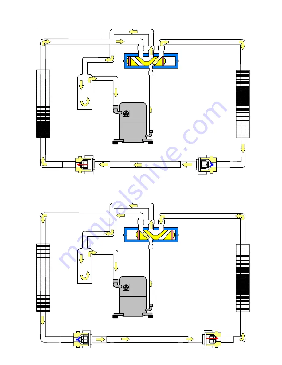
Indoor
Coil
Accumulator
Outdoor
Reversing Valve
(Energized)
(De-Energized)
TYPICAL HEAT PUMP SYSTEM IN HEATING
TYPICAL HEAT PUMP SYSTEM IN COOLING
Page 1: ...1 November2015 This manual is to be used by qualified professionally trained HVAC technicians only Goodman does not assume any responsibility for property damage or personal injury due to improper ser...
Page 2: ...8 FAN OPERATION 18 SCHEDULED MAINTENANCE 21 ONCE A MONTH 21 ONCE A YEAR 21 TEST EQUIPMENT 21 SERVICING 23 COOLING HEAT PUMP SERVICE ANALYSIS GUIDE 23 S 1 CHECKING VOLTAGE 24 S 2 CHECKING WIRING 24 S 3...
Page 3: ...S 109 CHECKING SUBCOOLING 35 S 111 FIXED ORIFICE RESTRICTION DEVICES 36 S 112 CHECKING RESTRICTED LIQUID LINE 36 S 113 REFRIGERANT OVERCHARGE 36 S 114NON CONDENSABLES 37 S 115 COMPRESSOR BURNOUT 37 S...
Page 4: ...H DO NOT STORE COMBUSTIBLE MATERIALS OR USE GASOLINE OR OTHER FLAMMABLE LIQUIDS OR VAPORS IN THE VICINITY OF THIS APPLIANCE WARNING GOODMAN WILL NOT BE RESPONSIBLE FOR ANY INJURY OR PROPERTY DAMAGE AR...
Page 5: ...could occur Under no circumstances is a hermetic compressor to be elec trically energized and or operated without having the terminal protective cover properly in place See Service Section S 17 for pr...
Page 6: ...al MODEL PACKAGE COOLING HEATING DESCRIPTION PC1524 60H41AA Amana Brand Goodman Brand or Distinctions Package Cooling 15 Seer 208 230 1 60 Single Phase Electric Cooling Unit with R 410A Initial releas...
Page 7: ...2 30 PC1542 22 30 PC1548 24 35 PC1560 24 35 Dimensions in inches Small Medium Chassis Model A B PH162441 22 000 29 932 PH163041 22 000 29 932 PH163641 24 000 34 932 PH164241 24 000 34 932 PH164841 24...
Page 8: ...unt Concentric Duct Kit w Filter CDK36530 Step Down Concentric Duct Kit CDK36535 Step Down Concentric Duct Kit w Filter CDK4872 Flush Mount Concentric Duct Kit CDK4872515 Flush Mount Concentric Duct K...
Page 9: ...ACCESSORIES 9 PCCP101 103 ROOF CURB PCP101 103 DOWNFLOW PLENUM Use with PCCP Roof Curb 64 33 26 33 59 14 Roof Curb 31 29 3 4 29 3 8 13 13 28 3 4 37 25 1 2 33 1 Flange PC15 PH16H41...
Page 10: ...LICATIONS 31 1 4 3 5 17 3 4 20 x 17 1 2 Filter 17 3 4 20 3 8 27 3 4 16 1 2 PCEF101 103 ELBOW AND FLASHING KIT 25 8 4 4 3 33 25 28 35 Must be used with PCP101 103 PC15 PH14641 Model Used With PCEC101 1...
Page 11: ...03 DOWNFLOW MOTORIZED DAMPER USEDWITHPCP101 103DOWNFLOWPLENUM GPHMD101 103 HORIZONTAL MANUAL DAMPER WITH DUCT FLANGE 18 29 3 4 6 10 12 1 8 6 2 12 25 1 4 17 17 1 4 18 8 1 4 MODEL DESCRIPTION PCMDH101 1...
Page 12: ...NGE BEAD SQUARE TO ROUND DUCT CONVERTER PANEL 1 1 2 29 1 2 29 1 4 RA SA 1 FLANGES SQRPC101 SQRP102 103 SA 16 18 RA 16 18 SQRPCH 101 SQRPCH 102 SQRPCH 103 SQRPCH102 14 SQRPCH103 14 A 15 17 17 15 15 B 1...
Page 13: ...ACCESSORIES 13 14 x 25 x 2 FILTER PCFR101 103 EXTERNAL FILTER KIT HORIZONTAL APPLICATIONS PC15 PH16H41...
Page 14: ...re proper condensate drainage unit must be in stalled in a level position The connecting ductwork Supply and Return can be connected for horizontal discharge airflow In the down discharge applica tion...
Page 15: ...il based lubricants like 3GS POE oil must be used if additional oil is required Compliant scroll compressors perform quiet shutdowns that allow the compressor to restart immediately without the need f...
Page 16: ...ange listed on the chart a If subcooling and superheat are low adjust TXV then check subcooling b If subcooling is low and superheat is high add charge to raise subcooling then check superheat c If su...
Page 17: ...120 41 500 134 130 45 525 138 140 49 550 142 150 53 575 145 160 56 600 149 170 60 625 152 SATURATED SUCTION PRESSURE TEMPERATURE CHART SATURATED LIQUID PRESSURE TEMPERATURE CHART TABLE 6 Suction Press...
Page 18: ...E The following only applies if the unit has an approved electric heat kit installed for auxiliary heating COOLING The refrigerant used in the system is R 410A It is a clear colorless non toxic and no...
Page 19: ...ys recognize the call for the highest speed and ignore the lower speed call If the thermostat is not calling for heat or cool and the fan switch on the thermostat is returned to the automatic posi tio...
Page 20: ...LING RESTRICTOR ORIFICE ASSEMBLY IN COOLING OPERATION In the cooling mode the orifice is pushed into its seat forcing refrigerant to flow through the metered hole in the center of the orifice Indoor C...
Page 21: ...RATION 21 Indoor Coil Accumulator Outdoor Coil Reversing Valve Energized Indoor Coil Accumulator Outdoor Coil Reversing Valve De Energized TYPICAL HEAT PUMP SYSTEM IN HEATING TYPICAL HEAT PUMP SYSTEM...
Page 22: ...ons are tight Inspect wire insulation to be certain that it is good 6 Check the contacts of the compressor contactor If they are burned or pitted replace the contactor 7 Using a halide or electronic l...
Page 23: ...Control Circuit w ith Voltmeter S 4 Low Voltage Test Voltage S 1 Faulty Evap Fan Motor Repair or Replace S 16 Shorted or Grounded Fan Motor Test Motor Windings S 16A D Improper Cooling Anticipator Che...
Page 24: ...alls below the minimum voltage check the line wire size Long runs of undersized wire can cause low voltage If wire size is adequate notify the local power company in regards to either low or high volt...
Page 25: ...wire around the stationary jaw of the amprobe and divide the reading by 10 10 TURNS OF THERMOSTAT WIRE From W on thermostat STATIONARY JAW OF AMPROBE READS 4 AMPS CURRENT DRAW WOULD BE 4 AMPS Checking...
Page 26: ...age personal injury or death The high pressure control senses the pressure in the liquid line If abnormally high discharge pressures develop the con tacts of the control open breaking the control circ...
Page 27: ...tor under certain operating conditions rather than having it discharge across the closing of the contacts within the switching device such as the Start Relay and to reduce the chance of shock to the s...
Page 28: ...d of the motor frame ground and the other probe in turn to each lead If the windings do not test continuous or a reading is obtained from any lead to ground replace the motor S 16D CHECKING EEM ENERGY...
Page 29: ...terminal without the presence of an external ignition source Therefore proper evacuation of a hermetic system is essen tial at the time of manufacture and during servicing To reduce the possibility of...
Page 30: ...ion breaks in the lead wires 4 If no visual problems indicated carefully remove the leads at the compressor terminals Carefully retest for ground directly between compressor terminals and ground 5 If...
Page 31: ...stem is on the COOLING cycle If no voltage is registered at the coil terminals check the op eration of the thermostat and the continuity of the connecting wiring from the O terminal of the thermostat...
Page 32: ...ANNER BEFORE APPLYING HEAT TO THE SYSTEM These models use the FasTest Access Fitting System with a saddle that is either soldered to the suction and liquid lines or is fastened with a locking nut to t...
Page 33: ...the most important part of the entire service procedure The life and efficiency of the equipment is dependent upon the thoroughness exercised by the serviceman when evacuating air non condensable and...
Page 34: ...for other operating condi tions Use it to provide the correct superheat at the conditions the unit is being charged at After superheat is adjusted it is recommended to check unit sub cooling at the c...
Page 35: ...echarge S 108 SUPERHEAT CHECKING SUPERHEAT Refrigerant gas is considered superheated whenever its tem perature is higher than the saturation temperature correspond ing to its pressure The degree of su...
Page 36: ...and clean or replace 3 Replace liquid line drier evacuate and recharge CHECKING EQUALIZATION TIME During the OFF cycle the high side pressure bleeds to the low side through the fixed orifice restrict...
Page 37: ...ll a suction line filter drier This drier should be installed as close to the compressor suction fitting as possible The filter must be accessible and be rechecked for a pressure drop after the system...
Page 38: ...60 8 6 162 0 57 0 264 0 87 4 366 0 110 4 468 0 129 0 600 0 149 0 62 10 0 164 0 57 7 266 0 87 9 368 0 110 8 470 0 129 3 604 0 149 5 64 11 3 166 0 58 4 268 0 88 4 370 0 111 2 472 0 129 7 608 0 150 1 66...
Page 39: ...308 90 88 86 84 82 80 317 92 90 88 86 84 82 326 94 92 90 88 86 84 335 96 94 92 90 88 86 345 98 96 94 92 90 88 354 100 98 96 94 92 90 364 102 100 98 96 94 92 374 104 102 100 98 96 94 384 106 104 102 10...
Page 40: ...not be used as a replacement for a 0 bleed valve due to the resulting drop in performance The bulb must be securely fastened with two straps to a clean straight section of the suction line Application...
Page 41: ...delivered through a given unit the less the rise will be so the less air CFM being delivered the greater the rise The temperature rise should be adjusted in accordance to a given unit specifications a...
Page 42: ...l 1 392 D Normal 1 392 D Plus 1 371 D Plus 1 371 D Plus 1 440 D Plus 1 440 C Minus 1 042 C Minus 1 042 C Minus 1 219 C Minus 1 219 C Normal 1 178 C Normal 1 178 C Normal 1 323 C Normal 1 323 C Plus 1...
Page 43: ...n 1395 A Off Off 1394 F B On Off 1499 C Off On 1605 D On On 1708 A Off Off 1500 F B On Off 1600 C Off On 1700 D On On 1800 F Factory Setting APC1548 APH1648 APC1560 APC1524 APH1624 APC1530 APH1630 APC...
Page 44: ...GEND BR C CH CM COMP EBTDR EM FC GND LVJB PLF RCCF SA TR HPS BLOWER INTERLOCK RELAY CONTACTOR CRACKCASE HEATER CONDENSER MOTOR COMPRESSOR ELECTRONIC BLOWER TIME DELAY RELAY EVAPORATOR MOTOR FAN CAPACI...
Page 45: ...OR CONDENSER MOTOR COMPRESSOR EVAPORATOR MOTOR EQUIPMENT GROUND LOW VOLTAGE JUNCTION BOX FEMALE PLUG CONNECTOR RUN CAPACITOR FOR COMPRESSOR AND FAN START ASSIST TRANSFORMER HIGH PRESSURE SWITCH COMPRE...
Page 46: ...TOR FOR COMPRESSOR AND FAN START ASSIST TRANSFORMER FACTORY WIRING LINE VOLTAGE LOW VOLTAGE OPTIONAL HIGH VOLTAGE FIELD WIRING HIGH VOLTAGE LOW VOLTAGE WIRE CODE BK BLACK BL BLUE BR BROWN GR GREEN OR...
Page 47: ...NG LINE VOLTAGE LOW VOLTAGE OPTIONAL HIGH VOLTAGE FIELD WIRING HIGH VOLTAGE LOW VOLTAGE WIRE CODE BK BLACK BL BLUE BR BROWN GR GREEN OR ORANGE PU PURPLE RD RED WH WHITE YL YELLOW SEE UNIT RATING PLATE...
Page 48: ...LD BE FACTORY EQUIPPED AS AN ALTERNATE CONFIGURATION 8 COMMON SIDE OF CONTACTOR CAN NOT BE GROUNDED OR CONNECTED TO ANY OTHER COMMON 24V SEE NOTE 5 SA SEE NOTE 4 RD YL BK OR GR 4 5 HPS CH CHS LPS YL P...
Page 49: ...IDE OF CONTACTOR CAN NOT BE GROUNDED OR CONNECTED TO ANY OTHER COMMON 24V SEE NOTE 5 SA SEE NOTE 4 RD YL BK OR GR 4 5 HPS CH CHS LPS YL PK PU RD RD CHS CH GR BK BK BK BK PU BK PU PU BL PK BL PK PU R W...
Page 50: ...PURPLE RD RED WH WHITE YL YELLOW FACTORY WIRING LINE VOLTAGE LOW VOLTAGE OPTIONAL HIGH VOLTAGE FIELD WIRING HIGH VOLTAGE LOW VOLTAGE NOTES 1 REPLACEMENT WIRE MUST BE SAME SIZE AND TYPE INSULATION AS O...
Page 51: ...YELLOW FACTORY WIRING LINE VOLTAGE LOW VOLTAGE OPTIONAL HIGH VOLTAGE FIELD WIRING HIGH VOLTAGE LOW VOLTAGE NOTES 1 REPLACEMENT WIRE MUST BE SAME SIZE AND TYPE INSULATION AS ORIGINAL AT LEAST 105 C USE...
Page 52: ...LOW VOLTAGE JUNCTION BOX BL W2 C R Y O W1 G E TYPICAL HP ROOM THERMOSTAT 1 2 OUTDOOR THERMOSTAT CLOSE ON TEMPERATURE FALL PACKAGE UNIT LOW VOLTAGE JUNCTION BOX BLUE BROWN WHITE ORANGE GREEN YELLOW RE...
Page 53: ...IRE R Y G O O Y G R BL BL BR W BR W 3 BL Y PACKAGE SYSTEM WIRING DIAGRAM HEAT PUMPS ONLY TWO STAGE ELECTRIC HEAT ABOVE 10 kW For outdoor temperatures below 0 F with 50 or higher relative humidity set...
Page 54: ...R 1 PLM ONE 1 ELEMENT ROWS TWO 2 ELEMENT ROWS FL M1 M2 FL FL M1 M2 M3 M4 5 KW 10 KW L1 BK BK L2 L1 L2 R Y M1 M2 BK R Y R R1 M4 R BK M3 HTR3 TL HTR2 HTR1 TL TL PU M2 R2 Y M1 BL W BR BL R BK R BK TL HTR...
Page 55: ...NSTALLING THIS UNIT MULTIPLE POWER SOURCES MAY BE PRESENT FAILURE TO DO SO MAY CAUSE PROPERTY DAMAGE PERSONAL INJURY OR DEATH PCE ECONOMIZER FOR PC PH H41 PC15 PH16H41 Wiring is subject to change Alwa...
Page 56: ...60 A A B B TO ELECTRIC HEAT A B B A NOTES 1 FOR APC GPC UNITS A L1 B L2 FOR APH GPH UNITS A L2 B L1 2 45 40 35 30 AMP BREAKERS WILL HAVE A PURPLE WIRE 50 AND 60 AMP BREAKERS WILL HAVE BLACK WIRE LABE...