

4
www.goodmanmfg.com
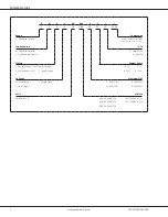
SS-GMVC80/GCVC80
SS-GMVC80/GCVC80
www.goodmanmfg.com
5
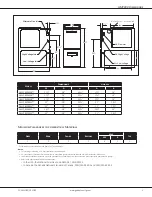
Minimum Clearances to Combustible Materials
Sides
Rear
Front
Bottom
Vent
Top
SW
B
1
0
3
C
6
1
1
C = If placed on combustible floor, the floor MUST be wood ONLY.
Notes:
•
For servicing or cleaning, a 24” front clearance is recommended.
•
Unit connections (electrical, flue, and drain) may necessitate greater clearances than the minimum clearances listed above.
•
In all cases, accessibility clearance must take precedence over clearances from the enclosure where accessibility clearances are greater.
•
Refer to the appropriate USA and Canadian codes:
͵ In the USA: the National Fuel Gas Code NFPA 54 / ANSI Z223.1
͵ In Canada: the Canada National Standard of Canada, CAN/CSA B149.1 and CAN/CSA B142.2
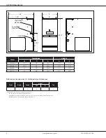
GMVC80 Dimensions
Model
Dimensions
Heights
W
D
H
A
B
GMVC800603B**
17½”
28”
33⅜"
17½”
16”
GMVC800604B**
17½”
28”
33⅜"
17½”
16”
GMVC800803B**
17½”
28”
33⅜"
17½”
16”
GMVC800804C**
21”
28”
33⅜"
21”
19½”
GMVC800805C**
21”
28”
33⅜"
21”
19½”
GMVC800805D**
24½”
28"
33⅜"
24½”
23"
GMVC801005C**
21”
28”
33⅜"
21”
19½”
28”
A
B
1¾”
33⅜”
23
5⁄16
”
1
7⁄16
”
13¼”
20”
27⅞”
Alt. Gas Inlet
Alt. High Voltage
Alt. Low Voltage
Alternate Gas Inlet
High-Voltage Inlet
Low-Voltage Inlet
Alt. Flue Outlet — Horizontal Left
➤
19½”
➤
➤
23”
➤
➤
15”
➤
➤