835961-UIM-B-0412
Johnson Controls Unitary Products
15
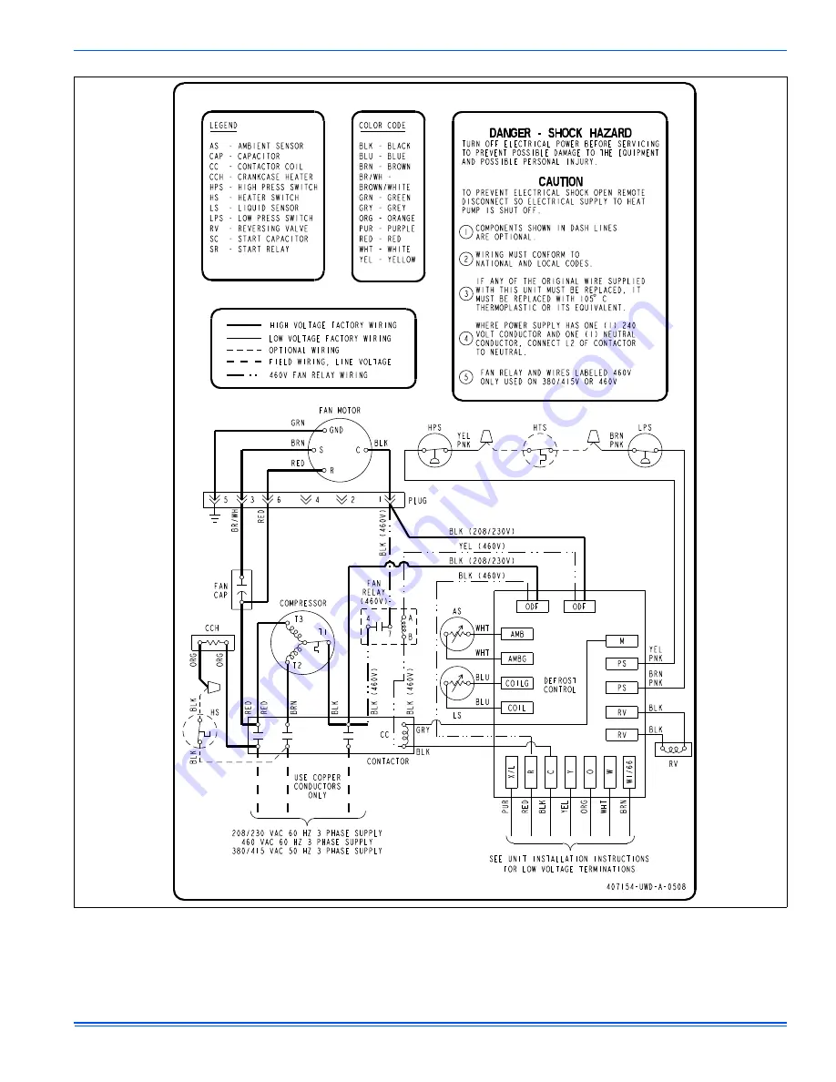
FIGURE 16:
Wiring Diagram - Three Phase (Demand Defrost)
*407154*
Page 1: ...may need to be changed for some indoor out door unit combinations elevation differences or total line lengths Refer to Application Data covering General Piping Recommendations and Refrigerant Line Length Part Number 247077 SECTION II SAFETY This is a safety alert symbol When you see this symbol on labels or in manuals be alert to the potential for personal injury Understand and pay particular atte...
Page 2: ...erformed in order to insure proper system operation and performance Line set change out is also recommended 1 Change out of the indoor coil to an approved R 410A coil con densing unit combination with the appropriate metering device 2 Change out of the line set when replacing an R 22 unit with an R410 A unit is highly recommended to reduce cross contamina tion of oils and refrigerants 3 If change ...
Page 3: ...s necessary If soft copper must be used care must be taken to avoid sharp bends which may cause a restriction 2 The lines should be installed so that they will not obstruct service access to the coil air handling system or filter 3 Care must also be taken to isolate the refrigerant lines to minimize noise transmission from the equipment to the structure 4 The vapor line must be insulated with a mi...
Page 4: ...rigerant piping connections including the service port flare caps to be sure they are leak tight DO NOT OVER TIGHTEN between 40 and 60 inch lbs maximum 9 Evacuate the vapor line evaporator and the liquid line to 500 microns or less 10 Replace cap on service ports Do not remove the flare caps from the service ports except when necessary for servicing the system 11 Release the refrigerant charge int...
Page 5: ...por line as follows a Hand tighten the 1 4 SAE nut to the Schrader fitting and an additional 1 3 turn to seal 7 Install the TXV bulb to the vapor line near the equalizer line using the bulb clamp s furnished with the TXV assembly Ensure the bulb is making maximum contact a Bulb should be installed on a horizontal run of the vapor line if possible On lines under 7 8 O D the bulb may be installed on...
Page 6: ...fic charging charts are provided on the access panel of the unit SECTION VIII ELECTRICAL CONNECTIONS GENERAL INFORMATION GROUNDING Check the electrical supply to be sure that it meets the values specified on the unit nameplate and wiring label Power wiring control low voltage wiring disconnect switches and over current protection must be supplied by the installer Wire size should be sized per NEC ...
Page 7: ...late Contactor Dual Run Fan Capacitor Fan Relay Defrost Control Board Ground Lug Fingered Bushing Low Voltage Box Reversible High Voltage Conduit Plate Contactor Fan Capacitor To eliminate erratic operation seal the hole in the wall at the ther mostat with permagum or equivalent to prevent air drafts affecting the operation of in the thermostat A Start Assist Kit is available and recommended for l...
Page 8: ...KCASE HEATER If this unit is equipped with a crankcase heater for the compressor a warning label with an adhesive back is supplied in the unit installation instruction packet This label should be attached to the field supplied disconnect switch where it will be easily seen In order to energize the crankcase heater set the indoor cooling ther mostat to the OFF position Close the line power disconne...
Page 9: ...58 164 73 211 88 266 103 331 118 407 59 167 74 214 89 270 104 336 119 412 FIGURE 10 Heat Pump Flow Diagram CHARGE COMPENSATOR Empty in cooling full in heating Not included in all Units FIELD CONNECTED LINE INDOOR COIL OUTDOOR COIL 4 WAY REVERSING VALVE FILTER DRYER Solid core SUCTION ACCUMULATOR LIQUID SENSOR COMPRESSOR BI FLOW TXV CHECK VALVE Cooling BI FLOW TXV CHECK VALVE OR ORIFICE Heating FIG...
Page 10: ...d the first stage of heat is turned on through W1 66 to continue warming the conditioned space The defrost cycle will be terminated when the defrost thermostat is opened at 55 F or 10 minutes of compressor accumulated run time whichever comes first Demand Defrost 13 Seer 1 5 ton 14 5 Seer 1 5 4 Ton The control maintains proper airflow through the outdoor coil during heating operation by melting fr...
Page 11: ...be bypassed and the compressor and the W1 66 terminal to auxiliary heat will be energized When the TEST inputs are used to force a defrost cycle the control will ignore the state of the liquid line temperature and outdoor ambient tem perature inputs The coil does not have to be cold and the outdoor tem perature does not have to be within a certain range for the heat pump to be forced into a defros...
Page 12: ...de energize the compres sor and energize the X L output with the appropriate flash code The control will reset the soft lockout condition when any of the follow ing occur following removal of the fault condition 1 Power is cycled to the R or Y inputs of the control This will cause the soft lockout condition to be reset when the thermostat is satis fied or when the thermostat is set to SYSTEM OFF a...
Page 13: ...835961 UIM B 0412 Johnson Controls Unitary Products 13 SECTION VII WIRING DIAGRAM FIGURE 14 Wiring Diagram Single Phase Demand Defrost ...
Page 14: ...ANGE PNK PINK PUR PURPLE RED RED WHT WHITE YEL YELLOW BLK BLK BRN PNK YEL PNK HPS HTS LPS BRN PNK YEL PNK YEL PNK SEE UNIT INSTALLATION INSTRUCTIONS FOR LOW VOLTAGE TERMINATIONS COND FAN X L PUR RED DEFROST CONTROL BLK WHT BRN BLK REV VALVE YEL ORG RV R C Y O W W1 66 PRES SWITCH DFST T STAT M BRN PNK YEL PNK BLK GRY LS BLU DANGER SHOCK HAZARD TURN OFF ELECTRICAL POWER BEFORE SERVICING TO PREVENT P...
Page 15: ...835961 UIM B 0412 Johnson Controls Unitary Products 15 FIGURE 16 Wiring Diagram Three Phase Demand Defrost 407154 ...
Page 16: ...LK ORG ORG B L K 4 6 0 V BLK 460V B L K 4 6 0 V BLK 460V RED BRN WHT BLK 208 230 BLK 208 230 BRN PNK YEL PNK HPS HTS LPS BRN PNK YEL PNK YEL PNK SEE UNIT INSTALLATION INSTRUCTIONS FOR LOW VOLTAGE TERMINATIONS COND FAN X L PUR RED DEFROST CONTROL BLK WHT BRN BLK REV VALVE YEL ORG RV R C Y O W W1 66 PRESS SWITCH DFST T STAT M BRN PNK GRY BLK YEL 460V BLK 460V LS BLU DANGER SHOCK HAZARD TURN OFF ELEC...