background image

5

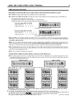
Description of the DIP switch and configuration of the Nhea terminal address (code):

DIP 1 to DIP 5:

Con

fi

gure the Nhea terminal address (up to 32 addresses).

DIP 1 to DIP 7:

DIP 10 set to ON

With

, it enables the Nhea terminal address to be con

fi

gured (up to 128 addresses).

The switches set to OFF have a zero value.
The values of the switches set to ON are shown in the table below.
The Nhea terminal code is the sum of the values of the switches set to ON.

DIP 8 and DIP 9:

Set the Nhea terminal as master/slave. DIP 8 and DIP 9 to OFF master, DIP 8 to ON and DIP 9 to

OFF slave 1, DIP 8 to OFF and DIP 9 to ON slave 2, DIP 8 and DIP 9 to ON slave 3.

If DIP 10 to ON, the Nhea

terminal is always 'master'.

DIP 10:

Leave in the OFF position for installations of up to 32 Nhea terminals (DIP 6 and DIP 7 without function). Set to

ON for installations of up to 128 Nhea terminals

, DIP 8 and

(EL632 GB2A/EL642 GB2A sound module required)

DIP 9 have no function, the Nhea terminal is always 'master' (maximum 1 Nhea terminal per apartment).

DIP 11:

Con

fi

gures the end of line. It should always be set to OFF in installations with only Nhea terminals. In mixed

installations with Nhea terminals in the same apartment, set to ON for the terminals in which the BUS cable ends and
set to OFF for intermediate terminals.

DIP 12:

Leave in the OFF position (no function).

NHEA GB2 HANDS-FREE AUDIO TERMINAL

TERMINAL DESCRIPTION:

1

2

3

ON

E

mpl : 0 + 0 +4+ 0+16 = 20

xa

e

Switch number:

1    2    3    4    5

1    2    4    8   16

Value when ON:

Table of values (DIP 10 to OFF)

4

5

6

7

8

9

10

11 12

1

2

3

ON

E

mpl : 1 + 2 +4+ 0 + 0 + 0 +64 = 71

xa

e

Switch number:

1    2    3    4    5    6    7

1    2    4    8   16  32  64

Value when ON:

Table of values (DIP 10 to ON)

4

5

6

7

8

9

10

11 12

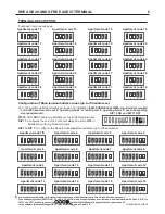
Configuration of Nhea terminal address codes (up to 32 addresses):

DIP 11:

Con

fi

gures the end of line. It should always be set to OFF in installations with only Nhea terminals. In mixed

installations with Nhea terminals in the same apartment, set to ON for the terminals in which the BUS cable ends and
set to OFF for intermediate terminals.

1

2

3

ON

4

5

Apartment code

1

1

2

3

ON

4

5

Apartment code

5

1

2

3

ON

4

5

Apartment code

9

1

2

3

ON

4

5

Apartment code

2

1

2

3

ON

4

5

Apartment code

6

1

2

3

ON

4

5

Apartment code

10

1

2

3

ON

4

5

Apartment code

3

1

2

3

ON

4

5

Apartment code

7

1

2

3

ON

4

5

Apartment code

11

1

2

3

ON

4

5

Apartment code

4

1

2

3

ON

4

5

Apartment code

8

1

2

3

ON

4

5

Apartment code

12

DIP 1 to DIP 5:

DIP 10 to OFF

To con

fi

gure the Nhea terminal/apartment address (up to 32 addresses) and

.

1

2

3

ON

4

5

6

DIP 11 to ON

DIP 11 to OFF

7

8

9 10

11

12

1

2

3

ON

4

5

6

7

8

9 10

11

12

Continued overleaf

( )

**

2

3

-

In door panel systems with call buttons, the first address on the Nhea terminal is 'Code 0' (see door panel manual).

-

In coded panel systems (N3301/GB2), 'Code 0' is 'Code 32', which means that when a call is made to a Nhea terminal with 'Code 0' (DIP 1 to

DIP 5 set to OFF), it needs to be entered

on the N3301/GB2 numeric keypad (see door panel manual).

In the software (Address Manager GB2), 'Code 0' is also shown as 'Code 32'.

IMPORTANT: In coded panel systems (N3301/GB2), an EL632 GB2A/EL642 GB2A sound module is required and must be configured
to 'operating mode 5' (see door panel manual).

( )

**

Summary of Contents for NHEA GB2

Page 1: ...USER MANUAL Code 50121929 T G 2 EN NHEA B REV 0 1 2 7 NHEA G 2 TERMINAL B TECHNOLOGY...

Page 2: ...ress codes up to 32 addresses 6 9 Configuration of terminal address codes up to 128 addresses 9 Front LED functions 10 Setting the ringtones 10 Intercom function 10 Do not disturb mode function 10 Lig...

Page 3: ...tivates the lock release for five seconds and LED on the door panel will also illuminate for five seconds If vocal synthesis is enabled a Door Opened message will be indicated on the door panel Descri...

Page 4: ...switch Microphone Speaker h i Connector fixings Bus connection terminals Horizontal cable entry DIP switch Hz connector h i j k l The terminal has a call volume control with maximum and minimum volume...

Page 5: ...f values DIP 10 to OFF 4 5 6 7 8 9 10 11 12 1 2 3 ON E mpl 1 2 4 0 0 0 64 71 xa e Switch number 1 2 3 4 5 6 7 1 2 4 8 16 32 64 Value when ON Table of values DIP 10 to ON 4 5 6 7 8 9 10 11 12 Configura...

Page 6: ...ode 9 6 7 1 2 3 ON 4 5 Apartment code 10 6 7 1 2 3 ON 4 5 Apartment code 11 6 7 1 2 3 ON 4 5 Apartment code 12 6 7 1 2 3 ON 4 5 Apartment code 13 6 7 1 2 3 ON 4 5 Apartment code 14 6 7 1 2 3 ON 4 5 Ap...

Page 7: ...0 6 7 Continued overleaf 1 2 3 ON 4 5 Apartment code 45 6 7 1 2 3 ON 4 5 Apartment code 46 6 7 1 2 3 ON 4 5 Apartment code 47 6 7 1 2 3 ON 4 5 Apartment code 48 6 7 1 2 3 ON 4 5 Apartment code 49 6 7...

Page 8: ...6 7 Continued overleaf 1 2 3 ON 4 5 Apartment code 89 6 7 1 2 3 ON 4 5 Apartment code 90 6 7 1 2 3 ON 4 5 Apartment code 91 6 7 1 2 3 ON 4 5 Apartment code 92 6 7 1 2 3 ON 4 5 Apartment code 93 6 7 1...

Page 9: ...de 123 6 7 1 2 3 ON 4 5 Apartment code 124 6 7 1 2 3 ON 4 5 Apartment code 125 6 7 1 2 3 ON 4 5 Apartment code 126 6 7 1 2 3 ON 4 5 Apartment code 127 6 7 1 2 3 ON 4 5 Apartment code 128 6 7 Continued...

Page 10: ...utton will light up and the terminal s being called in the apartment will ring to confirm that the call is being made The call needs to be answered within 40 seconds To establish communication press b...

Page 11: ...terminal Fixing the terminal s wall mounting connector to the wall Positioning the terminal 1 2 3 Avoid dusty or smoky environments or locations near sources of heat x 4 30 11 Connect the cables to th...

Page 12: ...with the screws supplied Positioning the embedding box and fitting the wall mounting connector Positioning the terminal Avoid dusty or smoky environments or locations near sources of heat Screws supp...

Page 13: ...EA Master AUX AUX NHEA BUS BUS BUS NHEA Master AUX NHEA Master AUX AUX NHEA Button panel ON 1 2 3 4 5 6 SW1 APARTMENT 1 APARTMENT 2 APARTMENT 32 For more information about the door panel installation...

Page 14: ...formation about the door panel installation configuration connection of an AC lock release 2nd lock release or mixed installation with monitors and Nhea terminals see the corresponding door panel manu...

Page 15: ...NOT S E 15 NHEA GB2 HANDS FREE AUDIO TERMINAL...

Page 16: ...olmar se reserva el derecho a cualquier modificaci n sin previo aviso Golmar se r serve le droit de toute modification sans pr avis Golmar reserves the right to make any modifications without prior no...

Reviews: