All contents copyright 2015, GOLDWING RC Version 1.0, Dec 2015
GOLDWING RC
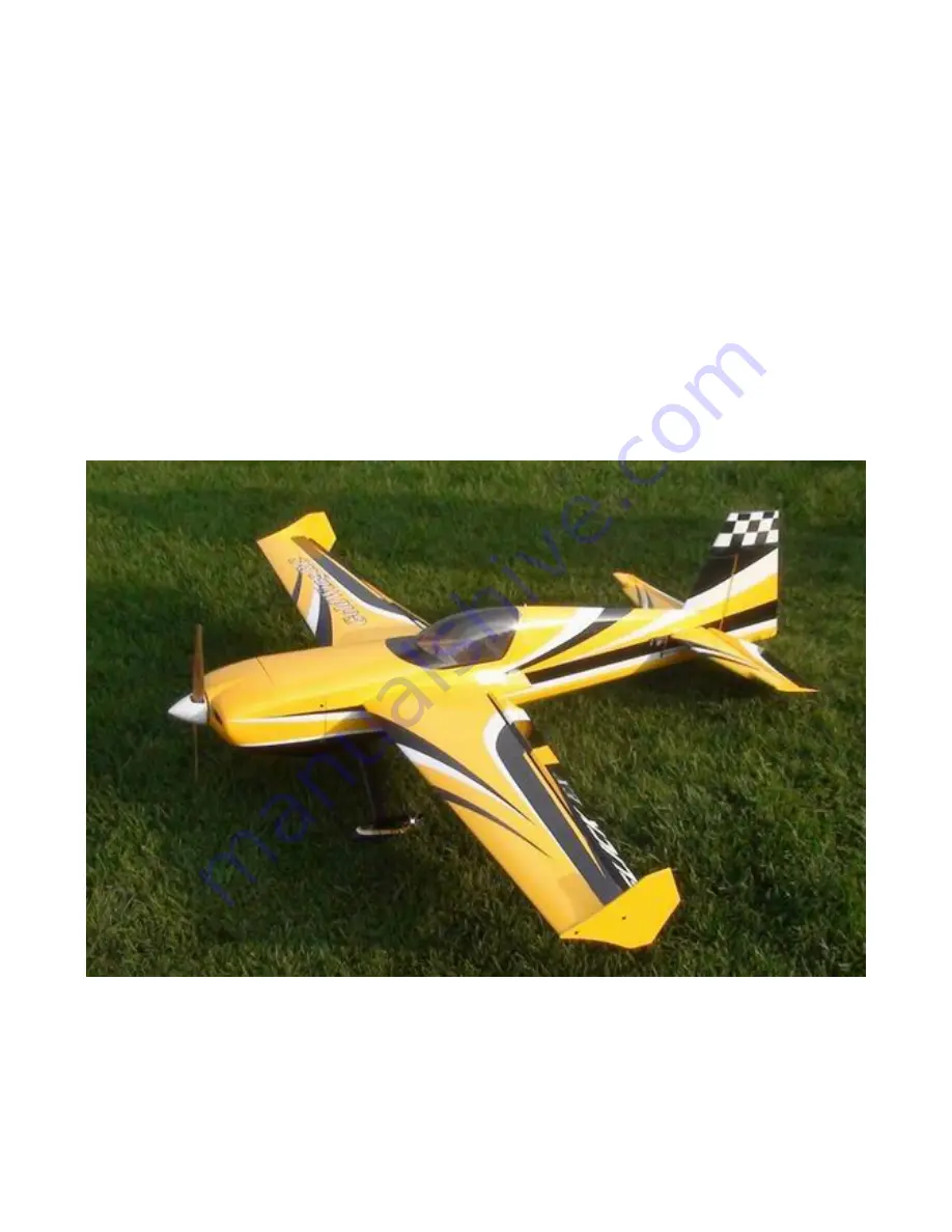
61in SLICK540 70E
Electric Extreme Series
Page 1: ...All contents copyright 2015 GOLDWING RC Version 1 0 Dec 2015 GOLDWING RC 61in SLICK540 70E Electric Extreme Series...
Page 2: ...recommended Propellers 500kv 15X8 450KV 16X8 Dear Customer Thank you for purchasing the new GoldWing RC Electric Extreme series aircraft This manual covers the 61 in SLICK540 70E aircraft It is a pre...
Page 3: ...surable but operators are You can obtain coverage through membership in the Academy of Model Aeronautics AMA For an AMA information package call 1 800 435 9262 ext 292 or visit the AMA website at www...
Page 4: ...es of throw on all control surfaces for excellent 3D aerobatic flying Pre hinged Control Surfaces Flat nylon hinges for better flying strength Honeycomb Board carton packing for safer transportation E...
Page 5: ...All contents copyright 2015 GOLDWING RC Version 1 0 Dec 2015 Improved new stainless steel Axles Side Force Generators KUZA Alloy Backplate Hollowed out Electric Spinner included...
Page 6: ...All contents copyright 2015 GOLDWING RC Version 1 0 Dec 2015 Quick release canopy latch Canopy extended into cowl Carbon Fiber accessories version Extra strength Carbon Fiber control Horns...
Page 7: ...l contents copyright 2015 GOLDWING RC Version 1 0 Dec 2015 One piece air foiled carbon fiber landing gear New Light Electric C F Tail wheel assembly Strengthened fuselage by carbon fiber board and rod...
Page 8: ...All contents copyright 2015 GOLDWING RC Version 1 0 Dec 2015 Larger carbon fiber wing tube diameter Scheme A Yellow white black...
Page 9: ...All contents copyright 2015 GOLDWING RC Version 1 0 Dec 2015 Scheme C White blue yellow...
Page 10: ...All contents copyright 2015 GOLDWING RC Version 1 0 Dec 2015 Scheme D White red blue...
Page 11: ...ue servos Hitec HS5245 or HS 7245 Appropriate servo arms KUZA heavy duty aluminum servo arms recommended Servo wire extensions two 6 two 24 Recommend KUZA Twisted 28 AWG Lightweight Servo Extensions N...
Page 12: ...raft Covering Varying temperatures and storage delays can cause covering material to loosen over time and transportation We recommend lightly going over all the covering with a covering iron set at me...
Page 13: ...this step Sealing the hinge gaps is therefore left as an option for modellers Please verify the accessories before assemble Carbon Fiber control Horns Bag No KA07NA2A 2 horns for ailerons 1 for elevat...
Page 14: ...All contents copyright 2015 GOLDWING RC Version 1 0 Dec 2015 New Light Electric C F Tail wheel assembly Bag No KAG0101 Pushrods kits Four 2x65mm pushrods for ailerons elevator rudder...
Page 15: ...copyright 2015 GOLDWING RC Version 1 0 Dec 2015 Ball link assembly Bag No KAG0011 8 PCS Servo lead safety clips Bag No KAG0019 4 pcs 2 25 main wheels Bag No KAG0146 2pcs New stainless steel Axle kits...
Page 16: ...ll contents copyright 2015 GOLDWING RC Version 1 0 Dec 2015 Extra covering provided for small repairs 3 Hex keys Bag No KA07NE Side force generators mounted with four M3X18 hand bolts and 2 wood sheet...
Page 17: ...ts copyright 2015 GOLDWING RC Version 1 0 Dec 2015 4 3x16mm hex head bolts Washers for landing gear mounting Screews Washers for cowl 4 2 5x12mm Hexagon socket screws 4 PTFE Washers Motor mounting har...
Page 18: ...ven by push rod servo bay is on the right side of the fuselage 1 2 Locate the slot for control horn on rudder remove the covering over the slot with heated soldering iron or sharp hobby knife and make...
Page 19: ...ntrol horn where will be glued into the slot 1 4 Fill the slot and coat the root of control horn and the bottom of base plate with 30 minute epoxy insert the horn into the slot press it down firmly Wi...
Page 20: ...er pre drilled it is advisable to apply some thin CA to strengthen them Install the servos and screw firmly in place 1 7 Use your radio to set the center of servo and then assemble and adjust the leng...
Page 21: ...ntents copyright 2015 GOLDWING RC Version 1 0 Dec 2015 1 8 We recommend using KUZA 1 25 aluminium CNC servo arm sold separately for rudder control 2 Landing Gear Installation 2 1 Locate the landing ge...
Page 22: ...the wheel axles to the landing gear and tighten the nylon insert lock nut Install one wheel collar onto the axle Use a second wheel collar as a guide to leave a gap on the inboard of the axle Use a s...
Page 23: ...using the 2mm hex head bolts Washers Use thread lock to secure the screws in place Repeat the above steps for the other main gear 2 5Tail wheel assembly for electric airplanes 2 6 Tail wheel kit is al...
Page 24: ...m rear of the fuselage secure the tailwheel bracket with the provided screws For best results the pivot point of the assembly should be over the hinge line of the rudder 2 8Drill a 4mm hole on the bot...
Page 25: ...wings ailerons are pre hinged in factory 3 2 Locate the slot for control horn on aileron remove the covering over the slot with heated soldering iron or sharp hobby knife and make sure you do it on th...
Page 26: ...o roughen up the root of control horn where will be glued into the slot 3 3 Fill the slot and coat the root of control horn and the bottom of base plate with 30 minute epoxy insert the horn into the s...
Page 27: ...ur radio to set the centers of each servo and then assemble and adjust the length of each control rod KUZA 1 aluminium CNC servo arm is recommended for aileron control sold separately The servo arm sh...
Page 28: ...ed in 1 2 1 4 to install control horns for elevators 4 2 Elevator horn slot is located on the left side of elevator Remove covering over the hole for horizontal stabilizer on fuselage Removing coverin...
Page 29: ...copyright 2015 GOLDWING RC Version 1 0 Dec 2015 4 3 Glue the nylon hinges for the elevator with epoxy glue 4 4 After installing the elevator use supplied balsa pieces to fill gap behind the elevator a...
Page 30: ...tion and install the large control horn onto the servo Assemble the control rod and ball links and adjust the control linkage for proper geometry When satisfied screw the ball link to the servo arm an...
Page 31: ...5 1 Find the hardware set for motor installation in the hardware package 5 2 Blind nuts are pre installed behind the firewall 5 3Since the position of cowl is fixed and length of motors varies you may...
Page 32: ...wl Installation 6 1 Test fit the cowl first make sure it fits well with canopy and fuselage 6 2 There are pre drilled screw holes on the cowl and the fuselage 6 3 Secure the cowl with 2 5X12mm self th...
Page 33: ...ht 7 2The fuselage ply sides provide space to mount your switches just below the canopy Mount your switches according to the manufacturer s instructions and route your wires safely and securely as abo...
Page 34: ...install each Note The best way to check your balance is to trim for level flight at about 1 2 to 3 4 throttle and then roll inverted The aircraft should maintain level flight with very little to no d...
Page 35: ...2015 are recommended Once you have the wings fully seated in the fuselage tighten the wing bolts inside the fuselage 9 3 Cut the wing film needed to be install the SFG Fixed the SFG Use M3X18 hand bo...
Page 36: ...for proper operation and installation 9 6 Check your batteries and perform a proper range check once again with the engine off and running Be sure all surfaces are moving in the correct direction and...
Page 37: ...G RC Version 1 0 Dec 2015 JR servo arms 26mm 1in for aileron No KAG0S70F KAG0S70H KAG0S70J 32mm 1 25in for elevator rudder No KAG0S71F KAG0S71H KAG0S71J KUZA new Wingbag for 70E Two color to choose or...
Page 38: ...All contents copyright 2015 GOLDWING RC Version 1 0 Dec 2015 www goldwingrc com...