gofanco 4K30 User Manual Download Page 26

26

Main Interface
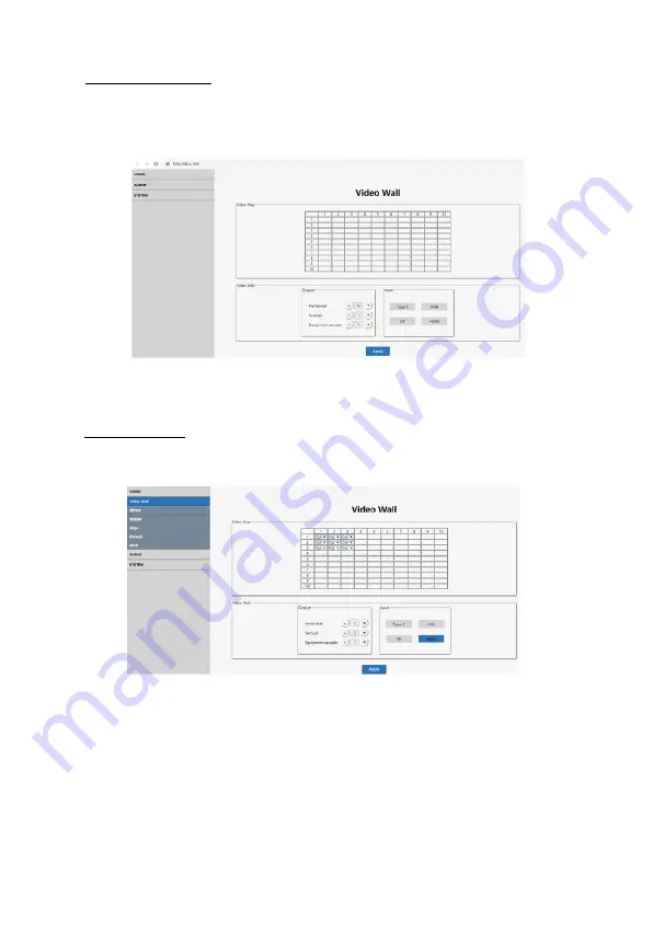
After login, the main interface is similar to the example

shown below.

Video Wall
This interface is used to setup video walls.

Video Map

: Identifies the location of the output

port mapping.  The output port can be changed

using the Output drop down box

Output

: Setting for Horizontal and Vertical directions

plus Cascade levels

Input

: Selects the video wall's source device

Summary of Contents for 4K30

Page 1: ...3x3 Video Wall Controller 4K30 User s Guide G4 0097A P N VideoWall33...

Page 2: ...Please pay close attention to all warnings and hints for this device Do not expose this unit to rain heavy moisture or liquid Do not put any items into the device or attempt to modify its operation D...

Page 3: ...ns Up to 4K 30Hz YUV 4 4 4 for all inputs Output resolutions Up to 4K 30Hz HDCP 2 2 1 4 compliant Controls Front panel buttons IR remote RS232 commands and LAN Supports S PDIF and Analog audio extract...

Page 4: ...d down to return to the main menu quick press to go back to the previous menu 6 Enter Right Quickpresstoenterthesub menu if thereisnosub menu shortpressconfirmsthesetting selection 7 Micro USB Connect...

Page 5: ...playPort source device 6 HDMIInput ConnectstoyourHDMIsourcedevice 7 Local HDMI Output Connects to your local HDMI display or the next Video Wall Controller for cascading 8 S PDIF Output Connects to yo...

Page 6: ...your VGA source s stereo audiooutputusinga3 5mm F to3 5mm F audio cable cable not included 6 Optional Connect speakers or AVR amplifier to the S PDIF output or Analog output ports 7 Optional Connect t...

Page 7: ...agram The application diagram shows the most typical input and output devices used with the 3x3 Video Wall Controller 4K30 Single Video Wall Controller Figure 3 Single Video Wall Controller Figure 3 3...

Page 8: ...8 Figure 4 6x4 Video Wall Daisy Chain Connection...

Page 9: ...roller using the included remote control Point the remote control at the Video Wall Controller s IR eye Figure 5 IR Remote Layout Note The operation of Right Enter on the remote is the same as the Rig...

Page 10: ...urce button to toggle through the four inputs in order Type C VGA DisplayPort HDMI Notes 1 The OSD interface shows four outputs and the active input channel 2 The OSD interface will automatically turn...

Page 11: ...n the switching menu 2 Press UP Down to select the input then press Menu Enter to confirm or go back to the previous menu 3 The selected input has the sign next to it as confirmation Notes In 1 USB Ty...

Page 12: ...panel to enter Video Wall menu 2 Press Up Down to select or set up the video wall mode 3 Press Enter Menu to confirm or go back to the previous menu 4 The selected video wall has the sign next to it...

Page 13: ...controller to the HDMI Input of the next controller Supports maximum of 12 layers Port Map Represents a display connected to an HDMI output Mirror Mode 1 Press Menu Left button on the front panel to...

Page 14: ...14 Rotate 1 Press Menu Left to enter Rotate menu 2 Each display supports 180 degree rotation select Yes or No 3 The option selected has the sign next to it...

Page 15: ...select then press Enter to confirm 3 The option selected has the sign next to it X Represents the space between the horizontal displays each image is divided into 302 units Y Represents the space betw...

Page 16: ...2 Press the Up or Down button on the controller s front panel to select then press Enter to confirm 3 The option selected has the sign next to it Resolutions 4K 30Hz 1080p 60Hz 720p 60Hz 2560x1440 192...

Page 17: ...panel to enter the EDID menu 2 Press the Up or Down button on the front panel to select then press Enter to confirm 3 The option selected has the sign next to it EDID Select 4K30 or 1080p 60Hz for ea...

Page 18: ...front panel to enter the Audio menu 2 Press the Up or Down button on the front panel to select then press Enter to confirm 3 The option selected has the sign next to it Notes The default setting is C...

Page 19: ...to enter the Audio menu 2 Press the Up or Down button on the front panel to select then press Enter to confirm 3 The option selected has the sign next to it Notes The default setting is Unmute and Del...

Page 20: ...e baud rate 115200 57600 19200 9600 then press Enter to confirm 3 The option selected has the sign next to it TCP IP 1 Press Menu Left on the controller s front panel to enter System menu then TCP IP...

Page 21: ...21 TCP IP Continued...

Page 22: ...Yes or No then press Enter to confirm 3 The option selected has the sign next to it Factory Reset Restores the 3x3 Video Wall Controller to factory default settings 1 Press Menu Left on the controller...

Page 23: ...23 System Information 1 Press Menu Left on the controller s front panel to enter System menu then INFO menu 2 Press the Enter button on the front panel to view IP and system information...

Page 24: ...o be in the same network segment Default IP address 192 168 1 168 Default subnet mask 255 255 255 Direct Control by PC 1 ConnectyourPC sEthernetporttotheEthernetport of the Video Wall Controller 2 Set...

Page 25: ...yping 192 168 1 168 in your browser and the login interface as shown below will open Type in username admin and password admin then click Login to enter the GUI Web Browser Compatibility Use the lates...

Page 26: ...deo Wall This interface is used to setup video walls Video Map Identifies the location of the output port mapping The output port can be changed using the Output drop down box Output SettingforHorizon...

Page 27: ...otate Allows image rotation of 180 degrees Select one image at a time or all at once A blue border indicates that a display is connected to the output port Edge The default for both horizontal and ver...

Page 28: ...theEDIDforeachinputportorallinput ports 1 Select the Input source or All in the output section 2 Select the EDID in the EDID section 3 Click Apply to save the changes 1 Select an HDMI Output or All in...

Page 29: ...elay the audio of one or all outputs The default setting is audio On and 30ms delay 1 Click on the or sign to adjust the delay 2 Click on the icon to mute or unmute the audio Audio Input AllowsPCM2 0o...

Page 30: ...not be modified Default setting IP address 192 168 1 168 DHCP Off Reset Allows you to restart the controller or restore it to the factory default settings Password Allows you to change the login pass...

Page 31: ...RS232 Control Software 1 Download the RS232 control software from www gofanco com downloads 2 Copy the control software files to the hard drive of your control PC 3 Double click the icon to open the p...

Page 32: ...16bit 24bit 44 1KHz 48KHz Input ports 1x USB Type C 1x DisplayPort 1x VGA 1x HDMI Output ports 9x HDMI 1x HDMI Loop out Splitter mode 1x9 HDMI splitter Video Wall modes 1x1 1x3 1x4 2x2 2x3 2x4 3x1 3x2...

Page 33: ...33 Blank Page...

Page 34: ...34 Blank Page...

Page 35: ...rs TM and may be omitted on the user s guide The pictures on the user s guide are just for reference and there may be some slight differences with the actual products We reserve the right to make chan...

Page 36: ...Thank you for choosing gofanco www gofanco com...

Reviews: