background image

37

5

    Maintenance and Adjustment

5.7    Cutter settings

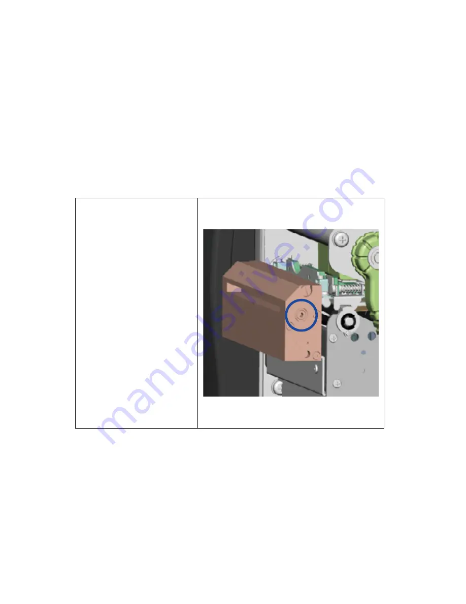
1.


Socket head screws for 

adjusting the cutter are 

located on both sides of the 

cutter. 


2.


In the event of a paper jam, 

the cutter will no longer 

function correctly. Switch 

off the printer and use a hex 

key (#M3) to turn the socket 

head screw. 


3.


Turn the key anticlockwise 

to remove the jammed 

paper. 


4.


When you have removed 

the jammed paper, you 

can switch the printer back 

on. The cutter will 

automatically reset. 


Note


The label medium should be at 

least 30 mm long to ensure 

correct functioning of the cutter. 


Summary of Contents for EZ2050

Page 1: ...1 EZ2050 EZ2150 BARCODE PRINTER USER MANUAL User Manual Version Issue Date P N EZ2050 series Rev D 2013 07 18 920 014411 00 ...

Page 2: ...alibration and Self Test 15 3 5 Dump mode 17 3 6 Error alerts 18 4 ACCESSORIES 19 4 1 internal rewinder 19 4 2 Installing the rewinder guide 21 4 3 Label dispenser 22 4 4 Installing the cutter 24 4 5 Installing the Parallel adapter 26 4 6 Installing the Applicator interface 28 5 MAINTENANCE AND ADJUSTMENT 30 5 1 Installing removing the print head module 30 5 2 Adjusting the print line 31 5 3 Adjus...

Page 3: ...tested and passed with the requirements relating to electromagnetic compatibility based on the standards EN 55022 2010 Class A EN61000 3 2 2006 A2 2009 EN 61000 3 3 2008 and EN 55024 1998 A1 2001 A2 2003 IEC 61000 4 2 2008 series The equipment also tested and passed in accordance with the European Standard EN55022 for the both Radiated and Conducted emissions limits EZ2050 SERIES TO WHICH THIS DEC...

Page 4: ... liquid on the equipment to avoid electrical shock 6 For safety and warranty reasons ONLY qualified service personnel should open the equipment 7 Do not repair or adjust energized equipment under any circumstances Safety instructions Danger of explosion if battery is incorrectly replaced Replace only with the equivalent type recommended by the manufacturer Dispose of used batteries according to th...

Page 5: ...nt Please check that all of the following items are included with your printer EZ2050 EZ2150 Barcode Printer USB Cable CD Including QLabel software and user manual Label Stock Ribbon Module Empty Ribbon Core Ribbon Power Adapter Power Cord EZ2050 Series Quick Guide EZ2050 EZ2150 Series ...

Page 6: ...r plate 3 Viewing window 4 Printer cover 4 3 1 2 1 Feed slot for continuous labels 2 Auto Calibration button 3 Parallel port optional 4 Applicator interface optional 5 NEthernet port 6 USB port 7 Serial port DB 9 8 On Off switch 9 Power jack 10 Feed slot for continuous labels 1 2 6 8 10 3 4 9 7 5 ...

Page 7: ...n rewind hub 2 Ribbon supply hub 3 Print mechanism 4 Platen roller 5 Tear off plate 6 Release lever for print head 7 Adjustment wheel for sensor 8 Paper guide 9 Label tension guide 10 Label supply hub 11 Label roll guide 12 Release catch 1 1 Movable sensor ...

Page 8: ... and alter the settings accordingly in the printer driver printer menu and or software 2 1 1 Place the printer on a flat surface and open the printer cover 2 Pull out the print head release lever as shown in the illustration 1 and turn it anticlockwise to a top right position 2 2 1 3 4 Pull the release catch for the label roll guide to the right as shown by the blue arrow 1 Now slide the label rol...

Page 9: ...Note When moving the label roll guide hold it only by the end that is attached to the bracket not by its top 7 Load the label roll into the printer as shown in the illustration Pass it through the printer as indicated by the blue arrows 1 2 3 8 Pass the label stock through the sensor and up to the tear off plate Note Remember to set the movable sensor to gap black mark or tag hole by changing the ...

Page 10: ... between the wall of the printer housing and the adjustable paper guide Note Pass the labels through the printer as shown in the illustration 10 Return the print head release lever to its original position 11 Then close the printer cover ...

Page 11: ...ght position 2 2 1 3 Place a new ribbon on the ribbon supply hub Then place an empty ribbon core on the ribbon rewind hub 4 The two illustrations on the right show you how to install the ribbon depending on the ribbon type ink side in or out Ink side out Ink side in 5 Pass the ribbon under the print head and back up on the other side Attach it to the empty ribbon core Note Do not pass the ribbon u...

Page 12: ...mputer 1 Please make sure that the printer is switched off 2 Connect the power cord to the AC adapter and connect the adapter to the printer 3 Connect the USB cable to the printer and host computer 4 Switch on the printer The operator panel should now light up ...

Page 13: ...elect the icon for the driver file and click it to start the installation 2 Follow the instructions on the screen The Driver Wizard guides you through the installation procedure Select Install printer drivers 3 Specify your printer model Godex EZ2050 Installing Printer Driver Directly from CD Folder 2 Printer Setup ...

Page 14: ...n is complete a summary of the printer settings is displayed Check whether the printer settings are correct and click Finish to start copying the driver files Wait until copying is complete then finish the installation 5 Enter a printer name and assign the appropriate rights Godex EZ2050 Godex EZ2050 Godex EZ2050 Godex EZ2050 ...

Page 15: ...11 2 Printer Setup 7 Once the driver installation is complete the new printer should appear in the Printers and Faxes folder Godex EZ2050 Godex EZ2050 ...

Page 16: ...ons FEED PAUSE CANCEL LED indicators POWER The POWER Ready LED lights up when the printer has started up and is ready to print RIBBON DENSITY 1 Ribbon status indicator 2 Density adjustment indicator in Setting Mode MEDIA SPEED 1 Media status indicator 2 Speed adjustment indicator in Setting Mode ...

Page 17: ...d To resume printing and print the remaining eight labels you press the PAUSE button again CANCEL button Pressing the CANCEL button during printing cancels a print job The current print job is cancelled Example While a 10 label print job is running you press the CANCEL button Two of the labels have been printed The print job is cancelled and the remaining eight labels are not printed You can combi...

Page 18: ...decide whether to save the changes you have made or exit without saving Once you have saved or discarded your changes the printer will switch back to standby mode Press the button and keep it pressed for about 3 4 seconds until you hear 3 beeps Blinking Steady DENSITY SPEED Description Start Exit Setting mode Exit withou t saving Save exit DENSITY and SPEED lights steady to indicator the strat or ...

Page 19: ...to go to next item Stop Position Decre ase the setting value Increas e the setting value DENSITY light blinks and Speed light flashes The buzzer will beep when the adjustment reaches the maximum or minimal Buzzer Off On When reaching this item press button to set the printer buzzer ON press button to set the printer buzzer OFF and press button to go back to Start Exit Setting mode Return to the St...

Page 20: ... a self test printout are listed below Model Version USB ID setting Serial port setting MAC address of Ethernet port IP protocol setting IP address of Ethernet port Gateway setting Netmask setting Number of DRAM installed Image buffer size Number of forms Number of graphics Number of fonts Number of Asian fonts Number of Databases Number of Scalable fonts Free memory size Speed Density Ref Point P...

Page 21: ...r start up or change label or ribbon to another type such as change using gap label to continuous or black mark labels Press CALIBRATION BUTTON Press C button for 2 seconds it will make an auto sensing to calibrate the label and ribbon s parameters Press Press C button is equivalent to the auto sensing command S SENSOR that will cancel on printing job and make the Label Calibration immediately ...

Page 22: ...r at all Here is how you switch to dump mode 1 Switch off the printer 2 Switch on the printer and keep the FEED button pressed 3 You will hear 3 beeps first and then one beep later Release the FEED button after the last beep The printer will automatically print Dump Mode Begin That means the printer is now in dump mode 4 Send commands to the printer and check whether they match the printer output ...

Page 23: ...ed Please make sure that the printer is set to thermal direct mode The ribbon is finished or the ribbon roll is not moving Replace the ribbon roll Out of media 1x2 beeps Unable to detect the paper Please make sure that the gap sensor is positioned correctly If that does not fix the problem run the auto detection function again The labels are finished Replace the label roll Paper jam Check the path...

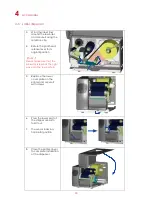
Page 24: ...4 4 Rewinder guide Note Maximum height of the rewound medium 118 mm Suggestion Medium thickness 0 06 mm 0 25 mm 1 Place the printer on a flat surface and open the printer cover Note Remember to switch off the printer before starting the installation 2 Remove the cover for the rewinder module ...

Page 25: ... clip from the rewinder 4 Secure the rewinder on the printer housing using the four screws supplied 1 2 5 Now connect the rewinder cable to the printer housing 6 Installation of the rewinder module is now complete 4 Accessories ...

Page 26: ...ews 4 Installation of the rewinder guide is now complete 5 Now load the label stock 6 Pass the label stock through the rewinder from the bottom up Secure the label stock on the rewinder using the retention clip Note Make sure you choose the correct rewind direction 7 Close the printer cover to complete the installation Note 1 Before you start using the rewinder please make sure that you have carri...

Page 27: ...o its original position Note Please make sure that the label stock rewinds the right way onto the rewind hub 2 3 1 5 Replace the lower cover plate on the printer and secure it with screws 6 Press the lower part of the stripper sensor to fold it out 7 The sensor locks in a horizontal position 8 Close the printer cover to complete installation of the dispenser ...

Page 28: ...al position Note Please make sure that the label stock rewinds the right way onto the rewind hub 2 3 1 10 Replace the lower cover plate on the printer and secure it with screws 11 Press the lower part of the stripper sensor to fold it out 12 The sensor locks in a horizontal position 13 Close the printer cover to complete installation of the dispenser ...

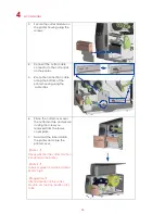
Page 29: ...e residue will be left on the cutter blade and impair its functioning The cutter has a blade life of 500 000 cuts when using paper weighing 160 g m and 250 000 cuts when using paper weighing 200 g m 1 Unscrew the screw marked in the illustration on the front of the printer which secures the lower cover plate 1 Remove the lower cover plate 2 Remove the two screws securing the tear off plate then re...

Page 30: ...housing using the cable clips 6 Place the cutter cover over the cutter module and secure it using the screw you removed from the lower cover plate 7 Now load the label roll into the printer and close the printer cover Note 1 Check whether the cutter function is enabled in the printer Note 2 Labels or paper should be at least 30 mm high Suggestion After installation of the cutter module set the sto...

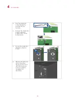
Page 31: ...le 4 Screws set of 2 1 Check whether the printer is switched off Place the printer on a flat surface and open the printer cover 2 Unscrew the two screws marked in the illustration on the right and remove the left hand side of the printer housing 3 Unscrew the screws on the parallel port cover and remove the cover ...

Page 32: ... it on the housing with screws 5 Connect the 30 pin connection cable to the motherboard 6 Replace the left hand part of the printer housing and secure it with the screws you removed earlier 7 Installation of the Parallel adapter is now complete 4 Accessories ...

Page 33: ...inter on a flat surface and open the printer cover Note Remember to switch off the printer before starting the installation 2 Unscrew the two screws marked in the illustration on the right and remove the left hand side of the printer housing 3 Unscrew the screws on the applicator interface cover and remove the cover ...

Page 34: ...to the housing 5 Connect the applicator cable to the jack marked APP on the motherboard 5 Secure the applicator interface using two screws 6 Replace the left hand part of the printer housing and secure it with the screws you removed earlier to complete the installation ...

Page 35: ...lease lever as shown in the illustration 1 and turn it anticlockwise to a top right position 2 2 1 3 Hold the print head module at the front and gently pull it out 4 If you cannot remove the module by gently pulling it use a screwdriver as shown in the illustration 5 Hold the module at the front and slide it into the printer along the guide rails Firmly press the module in so the contacts are full...

Page 36: ...nt line must be moved to the front in paper feed direction for a better print result Using a flat head screwdriver turn the screws clockwise to move the TPH forward The two screws on the left and right must be adjusted to the same position to ensure the print line and feed roller are in parallel One turn of the screw moves the print head by 0 5 mm To keep track of the change in quality you should ...

Page 37: ...ress in the knob and turn it clockwise or anticlockwise as required Increasing the tension of the ribbon rewind hub will remove any wrinkling of the ribbon during printing which results from the use of different ribbon materials For details about the wrinkling creasing of ribbons see Section 5 6 If you are using a very narrow ribbon the printer may not move the label stock forward particularly wit...

Page 38: ...ty and a longer lifespan of the print head Here is how you clean the print head 1 Switch off the printer 2 Open the printer cover 3 Remove the ribbon 4 Release the print head by turning the print head release lever 5 To remove any label residue or other dirt from the print head see blue arrow please use a soft lint free cloth dipped in alcohol Note 1 The print head should be cleaned once a week No...

Page 39: ...f there is no printed image on one side of the paper or the ribbon wrinkles the print head pressure must be readjusted using the TPH spring boxes 3 Move the TPH spring boxes as shown in the illustration to change the print head pressure The wider the medium you are using the further out the TPH spring boxes must be moved If there is no quality improvement you need to change the pressure on the TPH...

Page 40: ...A clockwise If your print result looks like the example in b you need to turn ribbon shield screw B clockwise a b 2 To keep track of the change in print quality you should adjust the screws by half a turn at a time Print a test page If there is no improvement in the print result turn the screw by another half turn Do not turn the adjustment screw more than two full turns Note If you adjust the scr...

Page 41: ...tter will no longer function correctly Switch off the printer and use a hex key M3 to turn the socket head screw 3 Turn the key anticlockwise to remove the jammed paper 4 When you have removed the jammed paper you can switch the printer back on The cutter will automatically reset Note The label medium should be at least 30 mm long to ensure correct functioning of the cutter ...

Page 42: ...ing position has been set incorrectly Check the ribbon for wrinkles There is no printed image on part of the label or the image is blurred Check the thermal print head for dust or other dirt Use the internal T command to check whether the thermal print head will carry out a complete print job Check the quality of the print medium The printed image is positioned incorrectly Check whether there is p...

Page 43: ...emarks and or registered trademarks of their respective owners Minimum print height and maximum print speed specification compliance can be dependent on non standard material variables such as label type thickness spacing liner construction etc Godex is pleased to test non standard materials for minimum print height and maximum print speed capability Appendix ...

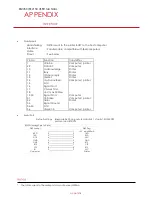
Page 44: ...0mA Parallel port EZ2050 EZ2150 USER MANUAL APPENDIX Handshaking DSTB is sent to the printer BUSY to the host computer Interface cable Parallel cable compatible with IBM computers Pinout See below Pin No Function Transmitter 1 2 9 10 11 12 13 14 15 16 17 18 19 30 31 32 33 34 35 36 Strobe Data 0 7 Acknowledge Busy Paper empty Select Auto Linefeed N C Signal Gnd Chassis Gnd 5V max 500mA Signal Gnd I...

Page 45: ... Ethernet module N C 1 1 N C TXD 2 2 RXD RXD 3 3 TXD CTS 4 4 RTS GND 5 5 GND RTS 6 6 CTS E_MD 7 7 E_MD RTS 8 8 CTS E_RST 9 9 E_RST 5V 10 10 5V GND 11 11 GND 5V 12 12 5V UART2 wafer Add on module N C 1 1 N C TXD 2 2 RXD RXD 3 3 TXD CTS 4 4 RTS GND 5 5 GND RTS 6 6 CTS N C 7 7 N C RTS 8 8 CTS N C 9 9 N C 5V 10 10 5V GND 11 11 GND 5V 12 12 5V Appendix ...

Page 46: ...150 USER MANUAL APPENDIX Applicator wafer Applicator module 5V 1 1 5V 24V 2 2 24V Printing out 3 3 Printing Print error out 4 4 Print error Printed out 5 5 Printed Print in 6 6 Print GND 7 7 GND N C 8 8 GND 9 9 N C 10 10 INTERFACE ...

Reviews: