background image

gpelectric.com  |  [page 9]

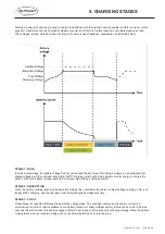
Maximum power point tracking is used to charge the batteries with the highest current possible, but this is only part of the 

equation. A battery cannot be charged at maximum power all the time for safety reasons, so multiple stages are used.

These stages include: bulk, absorption, float and, for some types of batteries, equalization as indicated below.


STAGE 1: BULK

In quick charge stage, the battery voltage has not yet reached the set value of full charge voltage (i.e. equalizing/boost 

charge voltage) and the controller will perform MPPT charging, which will provide maximum solar energy to charge the 

battery. When the battery voltage reaches the pre-set value, Stage 2 charge will start.

STAGE 2: ABSORPTION

When the battery voltage reaches the absorption voltage, the controller will perform constant voltage charging. This is no 

longer MPPT charging, and the charging current will gradually decrease with time.

STAGE 3: FLOAT

Float charge is conducted following the absorption charge stage. The controller will reduce the charge current to a 

small amount in order to reduce sulfates on the battery plates or to allow a lithium battery to balance it’s cells. If the load 

exceeds this small current the battery voltage will start to decrease until it reaches the recharge voltage. When the battery 

voltage falls below the recharge voltage, the controller will switch back to bulk charging.

5. CHARGING STAGES

Summary of Contents for 10 AMP RVC-MPPT

Page 1: ...olar Controller User Manual GP RVC 10 MPPT 2020 Go Power Worldwide Technical Support and Product Information gpelectric com Go Power 201 710 Redbrick Street Victoria BC V8T 5J3 Tel 1 866 247 6527 MAN_GP RVC 30 MPPT_RevA ...

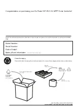
Page 2: ... Bank Information size install date battery type Product Packaging Please safely store the packing the product was delivered in or recycle the packaging components as outlined below LDPE Low Density Polyetheylene CFB 3 4 7 CFB 3 4 7 3 4 7 CFB 3 4 7 CFB 3 4 7 Corrugated fiberboard main box Plastic foam protection Plastic accessories bag www earth911 com recycling center search guides Local recyclin...

Page 3: ...ge 3 CONTENTS 1 SAFETY 4 2 INTRODUCTION 5 3 APPERANCE 6 4 MAXIMUM POWER POINT TECHNOLOGY 7 5 CHARGING STAGES 9 6 PRODUCT DIMENSIONS 12 7 SPECIFICATIONS 13 8 LED INDICATORS 14 9 INSTALLATION 15 10 RV C INSTANCE NUMBER 17 ...

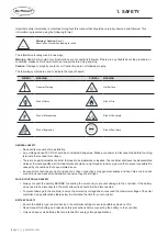
Page 4: ...vent possible fire caused by connections that have vibrated loose Ensure all connections are tight and secure Loose connections may generate sparks and heat Be sure to check connections one week after installation to ensure they are still tight SOLAR CONTROLLER SAFETY Always connect the battery BEFORE connecting the solar array to prevent damage to the controller If the battery wires need to be di...

Page 5: ...at the LCD remote can 2 2 FEATURES Advanced multi peak tracking technology When the solar panel is shadowed or part of the panel fails resulting in multiple peaks on the I V curve the controller is still able to accurately track the maximum power point Built in maximum power point tracking MPPT algorithm significantly increases energy utilization efficiency of the photovoltaic system up to 30 high...

Page 6: ...AME NO NAME 1 Instance Indicators 7 Battery Negative 2 PV Indicator 8 Extreme Temp Sensor 3 Battery Indicator 9 RV C Connector 4 Solar Positive 10 Remote Port 5 Solar Negative 11 Instance Config Button 6 Battery Positive 12 Installation Holes ...

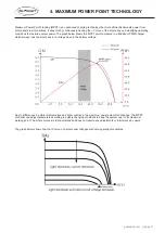
Page 7: ...al PWM charger which always runs the solar array at a voltage close to the battery voltage Due to differences in ambient temperature and light conditions the maximum power point often changes The MPPT controller can adjust parameters according to quickly changing conditions to keep the system near to its maximum working point The whole process is fully automatic and does not require any adjustment...

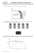
Page 8: ... there can also be multiple peaks in the P V curve that can confuse an MPPT algorithm Shown in the diagram below is a series string of solar panels A corresponding graph below shows lower maximum power points LMPP and the greater maxim power point GMPP that will result in maximum energy transfer The GP RVC series has a smart algorithm that will always choose the right peak ...

Page 9: ... charge the battery When the battery voltage reaches the pre set value Stage 2 charge will start STAGE 2 ABSORPTION When the battery voltage reaches the absorption voltage the controller will perform constant voltage charging This is no longer MPPT charging and the charging current will gradually decrease with time STAGE 3 FLOAT Float charge is conducted following the absorption charge stage The c...

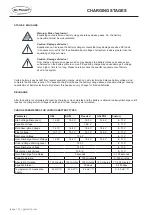
Page 10: ...e above a standard voltage causing vaporization of battery electrolyte By default this happens every 30 days for flooded batteries RECHARGE After the battery is completely charged the charging cycle completes and the battery is allowed to slowly discharge until it reaches the charge return voltage at which point a new charge cycle is initiated CHARGE PARAMETERS FOR VARIOUS BATTERY TYPES Parameter ...

Page 11: ...gpelectric com page 11 6 PRODUCT DIMENSIONS ...

Page 12: ...oss 10mA Grounding Negative Operating Temperature 35 to 45 C Storage Temperature 35 to 75 C Humidity 95 N C Battery Type Lead Acid AGM GEL Flooded LiFePO4 Max Wire Gauge 8 AWG Dimensions H x W x D 3 35 x 6 1 x 1 57 Weight 0 67lbs 300g Water Ingress Protection IP32 Altitude 3000m Protection Solar battery reverse polarity Solar battery over voltage Solar battery short circuit Over temperature 7 SPEC...

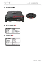
Page 13: ...ttery Fast Flash Battery over voltage Slow Flash Battery over discharged Steady On Battery status is ok 8 3 PV INDICATOR 2 LED PATTERN STATUS Off Night time Double flash Day time Single Flash No PV input Steady On MPPT charging Fast Flash Absorption or Equalize Slow Flash Float Charging 1 2 8 LED INDICATORS ...

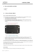
Page 14: ...fectively Locate the controller as close to the battery as possible but not directly above the battery to prevent potential damage due to gassing of the battery this will keep the battery wires short and prevent voltage drop Ensure any enclosed space where the controller is mounted is well ventilated this will prevent heat buildup that could lead to derating of the controller STEP 2 MARK THE MOUNT...

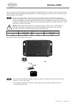
Page 15: ...n bus that is properly sized is recommended between the controller and battery do not stack wires on the battery terminals Warning Danger Electric shock hazards We strongly recommend connect a fuse or circuit breaker to the PV array and battery terminals to prevent electric shock hazards during wiring or error operation and make sure that fuse or circuit breaker is disconnected before wiring PV Ma...

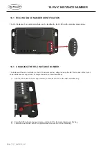
Page 16: ...ance of the solar controller on the RV C network can be configured using the SET button and LEDs Up to 5 unique instances are supported To change the instance follow these steps 1 Hold the SET button down for approximately 3 seconds until one of the LEDs starts flashing 2 Press the SET button to change instance until the LED for the desired instance is flashing 3 Press and hold the SET button for ...

Page 17: ...gpelectric com page 17 2020 Go Power Worldwide Technical Support and Product Information gpelectric com Go Power 201 710 Redbrick Street Victoria BC V8T 5J3 Tel 1 866 247 6527 MAN_GP RVC 30 MPPT_RevA ...

Reviews: