background image

Adjusting the depth of cut

Warning. 

Switch off the power and disconnect the plug

from the power point before servicing, when changing
accessories and when making adjustments.
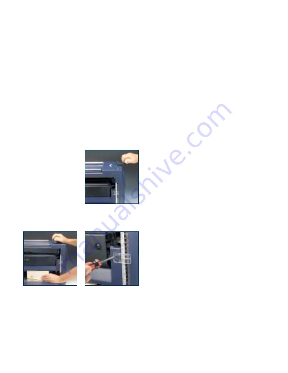
1. The depth of cut is changed by raising or lowering the

cutter head using the height adjusting handle (2).

2. The depth scale (3) shows the height of the cutter

head above the base of the machine.

Calibrating the depth scale

Warning. 

Switch off the power and disconnect the plug

from the power point before servicing, when changing
accessories and when making adjustments.
1. Raise the cutter head to 

its highest position using
the height adjusting 
handle (2)

2. Insert a wooden block of

known thickness (but less
than 150mm) under the
cutter head.

3. Lower the cutter head until

it just makes contact with the wooden block. Move the
block backwards and forwards across the width of the
cutter head to establish the optimum adjustment.

4. Loosen the screws securing the adjustable depth

indicator (4), adjust the indicator so that the scale
shows the correct height and re-tighten the screws.

5. Test the reading by planing a piece of scrap timber,

note the height indicated on the depth scale (3) and
then measure the thickness of the work piece. The two
measurements should be the same. If not, re-adjust
the depth indicator (4) accordingly.

Operation

1. Adjust the depth of cut to make an initial light

(0.5mm) cut. Note that one complete revolution of the
height adjusting handle (2) is equivalent to 2mm
depth of cut.

Warning.

Never attempt to plane more than 3mm in

one pass and never attempt to plan a board which is
less than 125mm long, or more than 160mm high, or
less than 4.5mm thick.

Warning.

Always use the push stick (16) to feed a

short work piece into the machine.

2. Switch on the machine and wait until the motor has

reached full speed.

3. Press the board against the in-feed table (6) and feed

it into the machine.

4. Release the board when the machine starts to cut and

let the board feed into the machine automatically.

5. Repeat the operation taking cuts of up to 3mm until

the desired thickness is achieved. Note that the finer
the cut, the better the finish.

Avoiding snipe

1. Snipe is caused by the board tilting slightly towards the

beginning and the end of the planing operation. 

2. It shows as lines at the ends of the board, parallel

with the cutter head. 

3. To avoid snipe, either support the board on extension

tables set to the same level as the in-feed and out-feed
tables, or mount the machine in a recess in the bench
so that the feed tables are level with the bench.

9

Summary of Contents for TP2000

Page 1: ...TP2000 031219 ED9 DR INSTRUCTION MANUAL 2000w 318mm 12 1 2 Planer Thicknesser Melbourne Perth Auckland Hong Kong Shanghai Taipei New York Verona London Paris ...

Page 2: ...d from the date of the original purchase If found to be defective in materials or workmanship the tool or the offending faulty component will be replaced free of charge with another of the same item A small freight charge may apply The warranty replacement unit is only made available by returning the tool to the place of purchase with a confirmed register receipt Proof of purchase is essential We ...

Page 3: ...erformance and dependability have been given top priority in the development of this tool making it easy to maintain and operate Environmental protection Recycle unwanted materials instead of disposing of them as waste All tools hoses and packaging should be sorted taken to the local recycling centre and disposed of in an environmentally safe way Description of symbols The rating plate on your too...

Page 4: ...rking at the rate for which it was designed 6 Use the correct tool for the job Do not force small tools or attachments to do the job best handled by a heavier duty tool Never use a tool for a purpose for which it was not intended 7 Dress correctly Do not wear loose clothing or jewellery They can be caught in moving parts Rubber gloves and non slip footwear are recommended when working outdoors If ...

Page 5: ...tage supply is the same as that specified on the nameplate of the tool A power source with a voltage greater than that specified for the tool can result in serious injury to the user as well as damage to the tool If in doubt do not plug in the tool Using a power source with a voltage less than the nameplate rating is harmful to the motor Always remove the plug from the mains socket before making a...

Page 6: ...when the tool is used as prescribed it is not possible to eliminate all residual risk factors The following hazards may arise in connection with the tool s construction and design Damage to the lungs if an effective dust mask is not worn Damage to hearing if effective earmuffs are not worn Damage to the eyes if effective eye protection is not worn Unpacking Due to modern mass production techniques...

Page 7: ...cator 5 Carry handle recess 6 In feed table 7 Overload switch 8 On Off power switch 9 Out feed table 10 Chip guard 11 Threaded posts for mounting the chip guard 12 Blade guide assembled 13 Mounting bolts x 4 14 Spanner 15 Hex keys 4mm and 5mm 16 Push stick 7 4 8 3 9 6 1 7 5 2 13 14 12 11 15 10 16 ...

Page 8: ...aution Make sure that the mounting surface is not warped as an uneven surface can cause inaccurate planing Switching on and off 1 For added safety the on off switch 8 includes a removable locking key to help prevent unauthorised use When the machine is left unattended remove the locking key and store it safely 2 To switch on insert the locking key and push the switch 8 to the ON position The motor...

Page 9: ...asure the thickness of the work piece The two measurements should be the same If not re adjust the depth indicator 4 accordingly Operation 1 Adjust the depth of cut to make an initial light 0 5mm cut Note that one complete revolution of the height adjusting handle 2 is equivalent to 2mm depth of cut Warning Never attempt to plane more than 3mm in one pass and never attempt to plan a board which is...

Page 10: ...Warning Switch off the power and disconnect the plug from the power point before servicing when changing accessories and when making adjustments 1 Make sure that the securing nuts in the slot in the cutter head are loosened i e turned clockwise 2 Fit the blade lock bar B into the slot with the 7 nuts on the side facing you and the thicker end of the bar at the bottom 3 Fit the blade A into the slo...

Page 11: ...the tabs at each bottom corner locates in the relevant slot in the machine base 7 Replace the handle 8 Check and reset the depth indicator if necessary General inspection 1 Regularly check that all the fixing screws are tight 2 The supply cord of the tool and any extension cord used should be checked frequently for damage If damaged have the cordset replaced by an authorised service facility Repla...

Page 12: ...ce to make suggestions or give comments about any GMC product With continuing product development changes may have occurred which render the product received slightly different to that shown in this instruction manual The manufacturer reserves the right to change specifications without notice Note Specifications may differ from country to country The GMC 777 Helpline operates from 7am to 7pm 7 day...

Reviews: