Operating Instructions
3-348-580-15
10/5.02
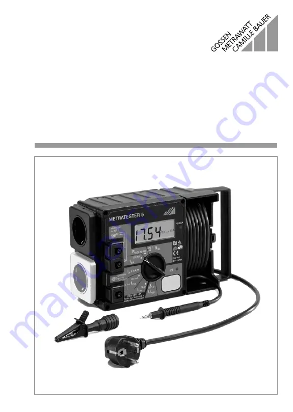
METRATESTER
â
4, 5 and 5-F
Tester for DIN VDE 0701-1:2000 and 0702:1995
Page 1: ...Operating Instructions 3 348 580 15 10 5 02 METRATESTERâ4 5 and 5 F Tester for DIN VDE 0701 1 2000 and 0702 1995 ...
Page 2: ... testing for the absence of voltage at conductive parts at the DUT per DIN VDE 0701 Part 240 7 Mains outlet 8 Test socket 9 Connector jack terminal for DUT phase conductors wired parallel to the socket 10 Connector jack terminal for DUT protective conductor wired parallel to test socket 11 LCD display description see page 29 12 Carrying handle 13 Error lamp METRATESTERâ 5 5 F only 14 Infrared inte...
Page 3: ...8 9 10 11 12 7 6 5 4 3 2 1 13 14 3a 15 IDiff mA INetz A MW RSL 0 3 1 0 RISO 0 5 2 0 IEA 7 0 15 IA 0 25 0 5 mA mA W IDiff mA INetz A Insulation Resistance P Resistance Equivalent Leakage Current Leakage Current Contact Current Residual Current Secondary Current Indication of Limit Values for DIN VDE 0702 1995 E ...
Page 4: ... I DUT with Mains Plug 11 4 4 2 Safety Class II DUT 11 4 4 3 DUT Without Mains Plug or Safety Class III DUT 11 4 4 4 3 Phase DUT 11 4 5 General Measuring Procedures 12 4 6 Residual Current Monitoring for METRATESTER 5 5 F only 12 5 Testing Devices per DIN VDE 0701 Part 1 2000 13 5 1 General 13 5 2 Visual Inspection 15 5 3 Measuring Protective Conductor Resistance 15 5 4 Measuring Insulation Resist...
Page 5: ...rt 240 21 7 1 General 21 7 2 Visual Inspection 21 7 3 Protective Conductor Test 21 7 4 Testing for the Absence of Voltage at User Accessible Exposed Conductive Parts 23 8 Measuring Load Current from the Mains Outlet 24 9 METRATESTER 5 Infrared Interface 25 10 METRATESTER 5 F Radio Interface 26 10 1 Applications 26 10 2 Initial Start Up 26 10 3 Using the Radio Interface 26 10 4 Radio Interface Char...
Page 6: ... at max 16A No measurements within electrical systems are allowed Be prepared for the occurrence of unexpected voltages at devices under test For exam ple capacitors may be dangerously charged Make certain that connector cables are not damaged e g damaged insulation interrup tions etc Attention Devices under test may only be connected to the mains outlet after they have successfully completed safe...
Page 7: ...Signal Lamp for Protective Conductor Testing The PE signal lamp lights up if a potential difference of 100 V occurs between the contacting surface 4 and the earthing contact at the mains plug 1 3 Alligator clip gripper clip for attachment to the test probe Connect the housing of the device under test with the alligator clip for measurement of pro tective conductor resistance 4 Contacting Surface f...
Page 8: ...ed out 13 Error Lamp The red error lamp indicates that limit values have been exceeded during the measurement of protective conductor and insulation resistance equivalent leakage contact and leakage cur rent as well as residual current The limit values apply for periodic testing in accordance with DIN VDE 0702 1995 KS 13 Accessory Cable Set The KS 13 cable set consists of a adapter socket with thr...
Page 9: ... contact socket is available or if only a three phase socket is available connection of the phase conductors the neutral conductor and the PE conductor can be accomplished with the help of the adapter socket It includes 3 permanently connected cables and is included with the KS 13 accessory cable set Attention The mains connection must be fused The fuse may not exceed a rating of 16 A The pick off...
Page 10: ... handling of the DUT which cause the PE signal lamp 3 to light up For example this may occur if a device is held in the hand which has been connected to the test socket 8 due to the resultant occurrence of a capacitive voltage divider Touch a grounded object as described above in this case Attention If testing of protective conductor potential indicates that voltage is present at the mains protect...
Page 11: ...onnected to the earthing contact at the test socket 8 Use one of the following test setups depending upon the type of device under test 4 4 1 Safety Class I DUT with Mains Plug 4 4 2 Safety Class II DUT 4 4 3 DUT Without Mains Plug or Safety Class III DUT 4 4 4 3 Phase DUT To test socket Switch the DUT on To housing for measurement of protective conductor resistance Test cable e g KS13 Switch the ...
Page 12: ... the event of a long term short circuit during insulation testing Excessive temperature is indicated at the display in this case see chapter 11 Display Excessive Temp If this display appears nominal current of 1 mA as required by DIN VDE 0413 and DIN VDE 0701 is no longer assured After the short circuit has been eliminated and after a brief cool down period the message is cleared from the display ...
Page 13: ... safety extra low voltage only at connecting points for safety extra low voltage generated within the device under test 4 Function test 5 Labelling inspection 6 Documentation Note Measurement of residual current is only possible with the METRATESTERâ 5 5 F Changes to DIN VDE 0701 1 1993 The standard has been completely revised as regards both layout and technical aspects Test procedures have been ...
Page 14: ...sed conductive parts are all connected to the protective conductor 0 5 mA for devices with exposed conductive parts which are not connected to the protective conductor Protective Conductor Current This test is required for all safety class I devices for which insulation resistance cannot be measured and for which all exposed conductive parts are connected to the protective conductor If non polariz...
Page 15: ...m the LCD Move the cable from the DUT during the measurement section by section over its entire length in order to locate interruptions Protective conductor resistance may not exceed the following values Maximum Allowable Protective Conductor Resistance Values Depending upon Cable Length Under no circumstances may a value of 1 W be exceeded The table is also valid for cable reels and extension cab...
Page 16: ...alent Leakage Current According to DIN VDE 0701 2000 it is absolutely essential to measure protective conductor current after insulation resistance measurement has been performed We recommend the use of an equivalent leakage current measurement Connection is the same as shown for the measurement of insulation resistance see chapter 5 4 page 16 Set the measuring range selector switch to the 20 mA p...
Page 17: ...as measured values 5 7 Measuring Residual Current METRATESTERâ5 5 F only Residual current differential current is measured between phase conductor L and neutral conductor N at the device under test This measurement may not be performed until the protective conductor test has been passed see chapter 5 3 page 15 Connect the device under test to the mains outlet Set the measuring range selector switc...
Page 18: ... Connect the device under test as described in chapter 4 4 page 11 Set the measuring range selector switch to the 20 W position Read the measured value in W from the LCD Move the cable at the DUT during the measurement section by section over its entire length in order to locate interruptions Protective conductor resistance may not exceed the following values Maximum Allowable Protective Conductor...
Page 19: ...e current measurement must be performed if the applicable limit value is fallen short of Attention If a value of 0 5 MW is fallen short of for safety class I devices with heating elements equivalent leakage current measurement must be performed and passed in accor dance with chapter 6 4 page 20 Each exposed conductive part must be contacted with the test probe connected to the jack 10 and insulati...
Page 20: ... parts which are not connected to the protective conductor Connect the device under test to the mains outlet Attention The protective conductor test must first be performed and passed Connect the cable with the test probe to the 2 mA jack Start up the device under test Contact all exposed metal parts at the device under test with the test probe Read the residual current value in mA from the displa...
Page 21: ...ged with voltage in the event of an error for individual devices with a mains plug Connect the device under test individual device to the mains outlet Set the measuring range selector switch to the 20 W position Read the measured value in W from the LCD Protective conductor resistance may not exceed 0 3 W Protective conductor resistance may not exceed 1 W for permanently installed data processing ...
Page 22: ...or combinations of permanently installed individual devices the network should be decoupled and individual measurements should be per formed If decoupling is not feasible individual measurements at interconnected devices may not demonstrate differences of greater than 0 2 W from device to device If this differential value is exceeded separate individual measurements are then required for each devi...
Page 23: ... data processing system or office machine must be disconnected from supply power in order to perform testing for the absence of voltage with the mains plug poled in both directions However the mains plug may only be pulled with approval from the responsible party A defect in the device under test may cause tripping of the residual current circuit breaker during testing which would also result in i...
Page 24: ...der test to the mains outlet 7 Set the measuring range selector switch 5 to the 16 A position Switch the device under test on Read the measured value in A from the LCD 11 Attention Maximum allowable load capacity is 16 A continuous and 20 A for up to 10 minutes The electrical system to which the test instrument is connected must be protected against overload with a fuse or circuit breaker The fuse...
Page 25: ...rface in compliance with IRDA per HP Design Guide Format 9600 baud 1 start bit 8 data bits 1 stop bit no parity no xon xoff no handshake Content device ID measured value measuring range alarm messages error per SK I and SK II Transmission Speed 2 5 times per second corresponds to measuring speed Alarm Messages 30h error free 31h protection class I error 32h protection class II error IRDA Message M...
Page 26: ...ission key at the test instrument after the completion of each mea surement in order to transmit measurement results to the PC The test instrument acknowledges transmission of the data with an acoustic signal i e after the third transmission of a complete data frame Continuous Measurement Press and hold the transmission key for at least 2 5 seconds The test instrument acknowledges activation of th...
Page 27: ...ector Pin Assignments The 9 pin Cannon connector at the receiver is configured as follows 1 NC 2 Data to PC receiver 3 Control wire auxiliary power 4 NC 5 Ground 6 NC 7 NC 8 NC 9 Power supply from PC 9 8 7 6 5 4 3 2 1 TxD GND 7 12 V DC ON OFF Measuring Range Switch code 0011 0001B 250 V 0011 0010B 16 A 0011 0011B open 0011 0100B I Diff 0011 0101B 2 mA 0011 0110B open 0011 0111B I EA 0011 1000B 20 ...
Page 28: ...9 mA 10 mA Meas Quantity Measuring Range Resolution Mains Voltage 207 253 V 1 V Load current at mains outlet 0 16 00 A 10 mA Load current at mains outlet residual current 19 A 5 min All other measuring quantities 250 V continuous Meas Quantity Intrinsic Error Service Error Protective Conductor Resistance 2 5 of rdg 2 D 10 5 D Insulation Resistance 0 1 999 MW 0 19 99 MW 2 5 of rdg 2 D 2 5 of rdg 2 ...
Page 29: ...rflow indicated at display with OL Excessive Temp RISO for long duration short circuit segments RISO and MW blink PE Signal Lamp Indicates whether or not voltage is present at the mains protective conductor Error Lamp The red error lamp indicates that limit values have been exceeded during the measurement of protective conductor or insulation resistance equivalent leakage contact or leakage curren...
Page 30: ... mA socket 1 5 kV Overvoltage Category II Contamination Level 2 EMC Interference Emission EN 61326 1 EMC Interference Immunity EN 61326 A1 Safety Cut Off when device overheats Ambient Conditions Operation 10 55 C Storage 25 70 C Atmosph Humidity max 75 Elevation to 2000 m Mechanical Design Protection Device IP 40 terminals IP 20 Dimensions W x H x D 190 mm x 140 mm x 95 mm Weight 1 3 kg 12 Mainten...
Page 31: ... our representatives or subsidiaries for service in other countries Calibration lab for electrical measuring quantities DKD K 19701 Accredited measuring quanities Direct voltage direct current intensity direct current resistance alternating voltage alternating current intensity alternating current active power alternating current apparent power direct current power capacity frequency 14 Product Su...
Page 32: ...n Germany Subject to change without notice GOSSEN METRAWATT GMBH Thomas Mann Str 16 20 90471 Nürnberg Germany Phone 49 911 8602 0 Fax 49 911 8602 669 e mail info gmc instruments com http www gmc instruments com ...