


5
221790B
1 General Data
Important Notice
This boiler is for use only on G20 gas.
All dimensions are given in millimetres (except as noted).
This boiler can be used only on an open vented system, with
either gravity or pumped domestic hot water connections to the
indirect cylinder.
Wherever possible, all materials, appliances and components
used shall comply with the requirements of applicable British
Standards.
Where no British Standard exists, materials and equipment
should be fit for their purpose and of suitable quality and
workmanship.
Sheet Metal Parts
WARNING. When installing or servicing this boiler care should
be taken when handling sheet metal parts, to avoid any possibility
of personal injury.
1.1 Statutory Requirements
The installation of the boiler must be carried out by a competent
person in accordance with the relevant requirements of the
current issue of:-
Manufacturer’s instructions, supplied.
The Gas Safety (Installation and Use) Regulations, The Building
Regulations, The Building Standards (Scotland) Regulations
(applicable in Scotland), Local Water Company Bye-laws, The
Health and Safety at Work Act, Control of Substances Hazardous
to Health, The Electricity at Work Regulations and any local
regulations which may apply.
Detailed recommendations are contained in the current issue of
the following British Standards and Codes of Practice:-
BS6798, BS5440 Part 1 and 2, BS5546 Part 1, BS5449, BS6891,
BS6700, BS7593, BS7478, BS7671.
Manufacturer’s instructions must not be taken as overriding
statutory requirements.
1.2 Data
See Table 1
1.3 Range Rating
This boiler is range rated and may be adjusted to suit individual
system requirements.
Table 2 gives the ratings and settings.
The Seasonal Efficiency Domestic Boilers UK (SEDBUK)
is 73%.
The value is used in the UK Government’s Standard Assessment
Procedure (SAP) for energy rating of dwellings. The test data
from which it has been calculated have been certified by B.S.I.
1.4 B.S.I. Certification
This boiler is certificated to the current issue of British Standard
6332 Part 1, invoking the current issue of BS5258 Part 1 for
performance and safety. It is, therefore, important that no
alteration is made to this boiler without permission, in writing,
from Hepworth Heating Ltd.
Any alteration that is not approved by Hepworth Heating Ltd.,
could invalidate the B.S.I. Certification of the boiler, warranty
and could also infringe the current issue of the Statutory
Requirements.
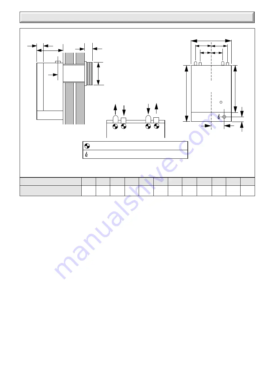
MODELS
50BF
Diagram 1.1
OVERALL DIMENSIONS (given in millmetres)
22mm COPPER PIPE
GAS CONNECTION RC
1
/
2
(
1
/
2
in. BSPT.)
A
B
C
D
M
SIDE ELEVATION
FRONT ELEVATION
FLOW GRAVITY
RETURN PUMPED
GRAVITY RETURN
PUMPED FLOW
E
CL
L
P
R
F
S
S
N
N
75
297
132 398
700 360
574
35
87
131
60
146
A
B
C
D
E
F
L
M
N
P
R
S


