


9 Start-up
32
Installation and maintenance instructions Energy
7
0020300875_01
9.11
Checking the gas setting
Only a qualified competent person is authorised to imple-
ment the settings on the gas valve assembly.
Each destroyed seal must be replaced.
The CO
₂
adjusting screw must be sealed.
Never modify the factory setting of the gas pressure regu-
lator of the gas valve assembly.
9.11.1 Checking the gas flow rate
The gas flow rate has been set during production and does
not require adjustment. With the front casing fitted check the
gas flow rate of the boiler as follows:
▶
Start up the product with the check programme
P.01
.
▶
In addition, ensure that maximum heat can be dissipated
into the heating system by turning up the room thermo-
stat.
▶
Wait at least 5 minutes until the boiler has reached its
operating temperature.
▶
Ensure that all other gas appliances in the property are
turned off.
▶
Measure the gas flow rate at the gas meter.
▶
Compare the measured values with the corresponding
values in the table.
Qnw from the data
plate
H gas in m
³
/h
Nom.
+5%
−
10%
15.3
1.62
1.70
1.46
18.4
1.95
2.05
1.76
24.7
2.61
2.74
2.35
25.7
2.72
2.86
2.45
28.6
3.03
3.18
2.73
30.6
3.24
3.40
2.92
35.7
3.78
3.97
3.40
Condition
: Gas flow rate not in the permissible range
▶
Check all of the piping and ensure that the gas flow rates
are correct.
▶
Only put the product into operation once the gas flow
rates have been corrected.
Condition
: Gas flow rate in the permissible range
▶
End the check programme
P.01
.
▶
Allow the boiler to cool down by allowing pump overrun to
operate for a minimum of 2 minutes.
▶
Record the boiler maximum gas flow rate onto the
Benchmark gas boiler commissioning checklist.
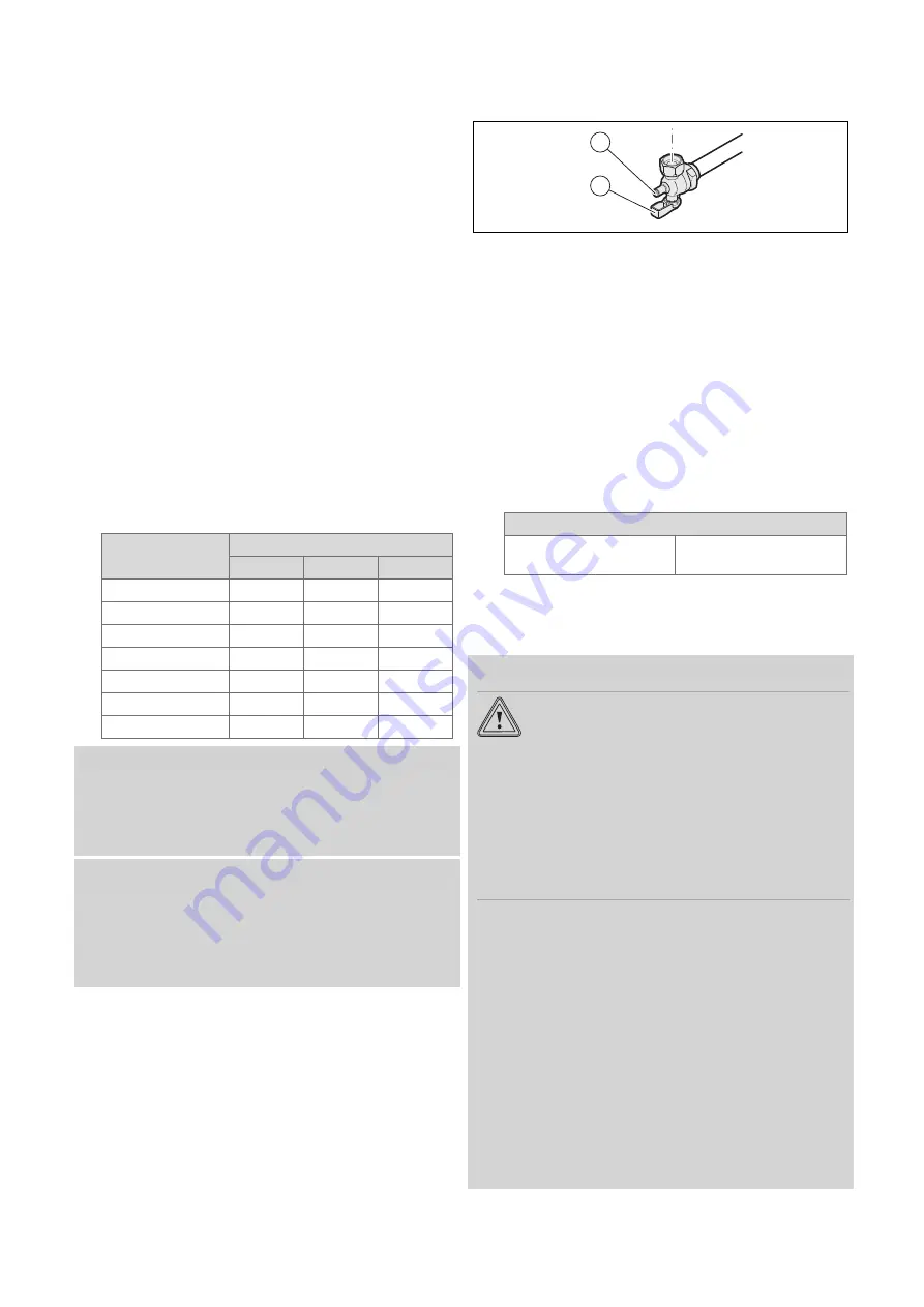
9.11.2 Checking the gas connection pressure (gas
flow pressure)
1
2
1.
Ensure that the gas inlet working pressure can be
obtained with all other gas appliances in the property
working.
2.
Close the gas stopcock
(1)
.
3.
Undo the sealing screw on the test nipple
(2)
.
4.
Connect a manometer to the test nipple
(2)
.
5.
Open the gas stopcock
(1)
.
6.
Start up the product with check programme
P.01
(in-
stallation with eBUS control).
7.
In addition, ensure that maximum heat can be dissip-
ated by fully opening one or more hot water taps.
8.
With the boiler operating at full load check that the gas
inlet working pressure at the reference test point
(2)
complies with the requirements.
Permissible gas flow pressure for operation with
Natural gas H
1.3 to 2.3 kPa
(13.0 to 23.0 mbar)
9.
Should the pressure recorded at the reference test point
in the boiler be lower than indicated check if there is
any blockage in the pipework or if the pipework is un-
dersized.
Condition
: Gas flow pressure
not
in the permissible range
Caution.
Risk of material damage and operating
faults caused by incorrect gas connec-
tion pressure.
If the gas connection pressure lies outside
the permissible range, this can cause oper-
ating faults in and damage to the product.
▶
Do not make any adjustments to the
product.
▶
Do not start up the product.
▶
If you cannot correct the failure, notify the gas supply
company and proceed as follows:
▶
End check programme P.01.
▶
Allow the boiler to cool down by allowing pump overrun
to operate for a minimum of two minutes.
▶
Close the gas stopcock.
▶
Remove the pressure gauge and retighten the sealing
screw
(2)
for the measuring nipple.
▶
Open the gas stopcock
(1)
.
▶
Check the test nipple for gas tightness.
▶
Close the gas stopcock
(1)
.
▶
Install the front casing. (
▶
Disconnect the product from the electrical installation.
▶
You must not start up the boiler.