Glow-worm Compact 24c-AS/1 H-GB Installation And Maintenance Instructions Manual Download Page 25

Start-up 9

0020289288_02 MicraCom Installation and maintenance instructions

25

If the entire filling and supplementary water quantity dur-
ing the operating life of the system exceeds three times
the nominal volume of the heating installation, or

If the guideline values listed in the following table are not
met, or

If the pH value of the heating water is less than 8.2 or
more than 10.0.

Total
heating
output

Water hardness at specific system volume

1)

20 l/kW

> 20 l/kW

50 l/kW

> 50 l/kW

kW

ppm

CaCO

mol/

m

³

ppm

CaCO

mol/

m

³

ppm

CaCO

mol/

m

³

< 50

< 300

< 3

200

2

2

0.02

> 50
to

200

200

2

150

1.5

2

0.02

> 200
to

600

150

1.5

2

0.02

2

0.02

> 600

2

0.02

2

0.02

2

0.02

1) Nominal capacity in litres/heating output; in the case of multi-
boiler systems, the smallest single heating output is to be used.

Caution.
Risk of material damage if the heating
water is treated with unsuitable additives.

Unsuitable additives may cause changes in
the components, noises in heating mode and
possibly subsequent damage.

Do not use any unsuitable antifreeze and
corrosion inhibitors, biocides or sealants.

No incompatibility with our products has been detected to
date with proper use of the following additives.

When using additives, follow the manufacturer's instruc-
tions without exception.

We accept no liability for the compatibility of any additive or
its effectiveness in the rest of the heating system.

Additives for cleaning measures (subsequent
flushing required)

Adey MC3+

Adey MC5

Fernox F3

Sentinel X 300

Sentinel X 400

Additives intended to remain permanently in the
installation

Adey MC1+

Fernox F1

Fernox F2

Sentinel X 100

Sentinel X 200

Additives for frost protection intended to remain
permanently in the installation

Adey MC ZERO

Fernox Antifreeze Alphi 11

Sentinel X 500

If you have used the above-mentioned additives, inform
the end user about the measures that are required.

Inform the end user about the measures required for frost
protection.

9.3

Filling the heating installation

Note

After each start-up, the product works at reduced
output when starting in order to facilitate the heat
transfer effect. This does not apply for check pro-
grammes and does not result in any loss of com-
fort for the end user. Status code

S.58

corres-

ponds to this phase. The display shows a tem-
perature of approx. 50 °C in this phase.

1.

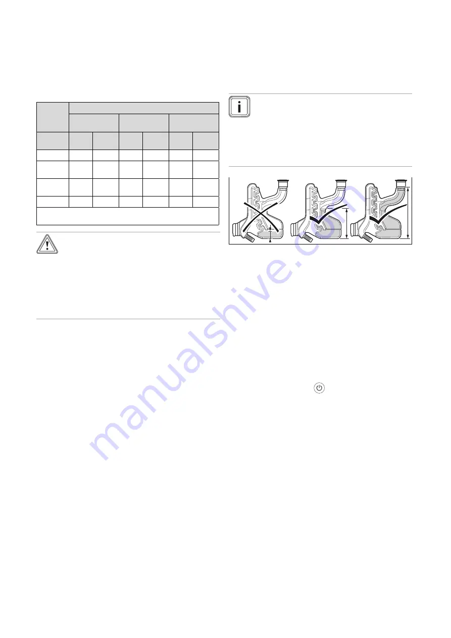
Ensure that the condensate siphon has been filled cor-
rectly.

2.

Before filling the heating installation, ensure that it has
been flushed out sufficiently.

3.

Connect the filling/draining cock in the heating install-
ation to a heating water supply in accordance with the
relevant standards.

4.

Open all of the thermostatic radiator valves and, if re-
quired, the service valves.

5.

Open the heating water supply and the filling tap so that
the heating water flows into the heating installation.

The heating circuit is automatically purged via the
hose that is connected to the pump.

Starting up the product

6.

Press the on/off button

.

The display shows the basic display.

7.

Start check programme

P.08

(

Page 24)

Check programmes (

Page 48)

The product's heating circuit is automatically purged
via the hose that is connected to the pump.

8.

Purge the highest radiator until water flows out of the
purging valve without bubbles.

9.

Purge all other radiators until the entire heating installa-
tion has been completely filled with heating water.

10. Close all purging valves.
11. Fill with heating water until the required filling pressure

is reached.

0.10 to 0.14 MPa (1.00 to 1.40 bar)

If the heating installation extends over several
storeys, higher filling pressures may be required to
avoid air entering the heating installation.

12. Close the filling tap and the heating water supply.
13. Check all of the connections and the entire circuit for

leaks.

Summary of Contents for Compact 24c-AS/1 H-GB

Page 1: ...Installation and main tenance instructions MicraCom 24c AS 1 28c AS 1 GB IE...

Page 2: ...Start up 24 9 1 Carrying out the initial start up 24 9 2 Checking and treating the heating water filling and supplementary water 24 9 3 Filling the heating installation 25 9 4 Purging the heating inst...

Page 3: ...w The following work must only be carried out by competent persons who are sufficiently qualified to do so Set up Dismantling Installation Start up Inspection and maintenance Repair Decommissioning Pr...

Page 4: ...sufficient in accordance with the relevant ventilation requirements This also applies in particular for cupboard installa tions To prevent corrosion on the product and in the flue system Ensure that t...

Page 5: ...eat generator circuit 1 3 9 Neutralisation device To prevent contamination of the waste water Check whether a neutralising unit must be installed in accordance with national regulations Observe local...

Page 6: ...enquiries vaillant group com Spares Enquiries Telephone 01773 881383 To register your Glow worm appliance visit Glow worm is a licensed member of the Benchmark Scheme Benchmark places responsibilitie...

Page 7: ...w at 15 C and 1013 mbar based on domestic hot water generation G31 1 86 kg h 2 18 kg h Permissible installation types C13 C33 C43 C53 C13 C33 C43 C53 Nominal efficiency in partial load mode 30 107 8 1...

Page 8: ...l Technical data Domestic hot water 24c AS 1 28c AS 1 Minimum water flow 1 7 l min 1 7 l min Specific flow rate D T 30 K 11 5 l min 13 4 l min Specific flow rate D T 35 K 9 9 l min 11 5 l min Permissi...

Page 9: ...ation of the central heating If the boiler does not resume normal operation reset the boiler If the boiler does not resume normal operation after this call your Installation Servicing company or Glow...

Page 10: ...Maximum heat output in domestic hot water generation mode Qnw Maximum heat input in domestic hot water generation mode Hi Lower gross calorific value Barcode with serial number 3rd to 6th digits produ...

Page 11: ...ducts are only certified and can only be fitted with a concentric flue system 6 5 Air flue pipe 6 5 1 Regulation Different flue outlet configurations can be carried out Consult the installation manual...

Page 12: ...is required if persons could come into con tact with the terminal or the terminal could be subject to dam age If a terminal guard is required it must be positioned to provide minimum of 50 mm clearanc...

Page 13: ...clearance to noncombustible building material Vertical flue clearance to combustible building material 500 mm 1 500 mm J Above below and either side of an opening door air vent or opening window 300 m...

Page 14: ...distance of the terminal 2 These dimensions comply with the building regulations but they may need to be increased to avoid wall staining and nuisance from pluming depending on site conditions Termina...

Page 15: ...nance instructions 15 Balcony eaves Gutter Adequately secured air flue gas pipe The flue pipe must protrude beyond any overhang You can use a plume management kit to enable the termination point to be...

Page 16: ...ing 1 elbow 0 3 m including 1 elbow Max length L 16 m including 1 elbow 20 m including 1 elbow Max height H 2 10 m 2 10 m Equivalence to 1 elbow 90 2 5 m 2 5 m Equivalence to 1 elbow 45 1 m 1 m 6 5 4...

Page 17: ...m Each time an additional 90 bend is necessary or 2 at 45 the length L must be reduced see table below 60 100 24c AS 1 28c AS 1 Min length L 0 3 m 0 3 m Max length L 3 m 3 elbow 3 m 3 elbow 60 100 24c...

Page 18: ...pipes if they have not yet been connected to the product 7 1 Requirements 7 1 1 Carrying out basic preparation for the installation 1 Make sure that the existing gas meter is capable of passing the r...

Page 19: ...phon may be drained fully and flue gas may escape Have the condensate discharge hose end outside of the waste water pipework A B 1 Follow the instructions listed here and observe the legal and local r...

Page 20: ...tube 5 Limestone chippings 6 Hole depth 400 mm minimum Least preferred option must not terminate in rain water drain 7 5 6 Internal termination downstream of sink waste 100mm 32mm 22mm 3 m Open end of...

Page 21: ...out which air flue pipes may be used by consulting the enclosed set up instructions for the air flue system Condition Installation in damp rooms Connect the product to a room sealed air flue system T...

Page 22: ...grommet is plugged in correctly and that the cables have been routed correctly 3 Ensure that the grommets envelop the connection cables tightly and with no visible gaps 4 Use the strain reliefs 5 If r...

Page 23: ...ntrol 24 V ON OFF 3 eBUS control or radio receiver unit 4 Outdoor temperature sensor wired 5 eBUS control or radio receiver unit 1 Carry out the wiring Page 22 2 Alternatives 1 Connecting the weather...

Page 24: ...start up Initial start up must be carried out by a customer service technician or an authorised competent person using the Benchmark Checklist The Benchmark Checklist in the ap pendix Page 50 of the i...

Page 25: ...ed the above mentioned additives inform the end user about the measures that are required Inform the end user about the measures required for frost protection 9 3 Filling the heating installation Note...

Page 26: ...2 in the sup ply air search for the leak in the flue system or for signs of flue gas recirculation 5 Eliminate the damage properly 6 Check again whether the supply air contains any unusal levels of CO...

Page 27: ...1 kPa 1 mbar lower than the minimum value spe cified in the table Result 1 Gas connection pressure gas flow pressure in the per missible range Temporarily decommission the product Page 39 Hinge the el...

Page 28: ...instead report this to customer service Result 2 If the value is inside the permitted range Continue with the process of starting up the product 6 Remove the sensor for the CO analyser and close the...

Page 29: ...he system is to be treated with an inhibitor it should be applied at this stage in accordance with the manufacturer s instructions See the section on checking and preparing the heating water Page 24 8...

Page 30: ...Notes application Right hand stop turned all the way down 0 035 MPa 0 350 bar If the radiators do not heat up sufficiently at the factory setting In this case you must set the pump to the maximum spee...

Page 31: ...off the guarantee documentation 12 Inspection and maintenance Adhere to the minimum inspection and maintenance in tervals Carry out maintenance work on the product at an earlier point if the results...

Page 32: ...the expansion vessel to the maintenance position 12 3 Moving the expansion vessel to the maintenance position on the hydraulic block A C A B D Depending on the components on which you want to work mo...

Page 33: ...sts of four main components Gas valve assembly Venturi and restrictor for the reference pressure pipe Burner flange Premix burner 1 Never remove the venturi from the burner flange x4 3 5 4 2 1 6 2 Rem...

Page 34: ...iphon 3 Check the insulating mat 3 on the burner flange for damage Result Insulating mat damaged Replace the insulating mat Spare parts instruc tions for the heat exchanger insulating mat 12 4 4 Check...

Page 35: ...5 0 5 mm 6 Replace the seal 3 7 Install the electrode To do this proceed in reverse or der 12 4 7 Checking and cleaning the restrictor for the reference pressure pipe 0 23 D 65 150 A B C E 1 2 3 1 Rem...

Page 36: ...ng filter under running water against the direction of flow 7 If the strainer is damaged or it can no longer be cleaned sufficiently you must replace the strainer 8 Use only new seals 9 Reinsert the h...

Page 37: ...ge 44 Press and hold the button for longer than three seconds to reset the product maximum five times rE is shown in the display rE flashes rapidly after five reset attempts Press to stop the flashing...

Page 38: ...starting the product carry out a leak tightness test check the CO content and if required adjust this 13 4 4 Replacing the fan 1 Move the expansion vessel to the maintenance position on the combustion...

Page 39: ...Press the on off button The display shows oF and then goes out 3 Disconnect the product from the mains power 4 Close the gas stopcock 5 Close the stopcock on the cold water connection 15 Recycling an...

Page 40: ...charge pressure of the expansion vessel at regular intervals 35 12 Removing the compact thermal module at regular intervals 33 13 Cleaning the heat exchanger at regular intervals 34 14 Checking the b...

Page 41: ...nt value Hi 100 d 16 Status of the 24 V room thermostat ON OFF Current value OF Heating off on Heating on or eBUS control used d 17 Heating control 0 Flow temperature 1 Return temperature adjustment f...

Page 42: ...ent 100 Fan speed Display value x 1000 flashing 1000 1 0 x 1000 d 58 Solar circuit reheating 0 3 Applies to Installed solar set optional 0 Product s anti legionella function deactivated 3 Domestic hot...

Page 43: ...ner for heating mode is activated S 05 The pump and fan overrun for heating mode is activated S 06 The fan overrun for heating mode is activated S 07 The pump overrun for heating mode is activated S 0...

Page 44: ...rat ure sensor Flow temperature sensor de fective Replace the flow temperature sensor Multiple plug loose not plugged in Check the multiple plug and plug connection Interruption in the cable harness C...

Page 45: ...ion location of the non return valve F 25 Safety shutdown Flue gas tem perature too high Flue gas safety cut out plug is not plugged in or is loose Check the plug and the plug connection Interruption...

Page 46: ...PCB Temperature sensors defective or not connected correctly Ensure that the electrical connection for the temperature sensors has been established correctly that they are not corroded and that they...

Page 47: ...w temperature sensor F 72 Fault Return temperature sensor Flow temperature sensor de fective Replace the flow temperature sensor Return temperature sensor de fective Replace the return temperature sen...

Page 48: ...assembly Short circuit in the cable har ness Check the cable harness F 89 Fault Pump Pump not connected Check the pump connection Pump connected incorrectly Check the pump connection Incorrect pump co...

Page 49: ...4V 230V 24V 230V 2 12 13 14 16 1 8 9 10 11 15 17 18 17 3 4 5 6 X32 eBUS 1 3 2 4 7 1 Main PCB 2 PCB for the control element 3 Limit thermostat with contact for underfloor heating Burner off optional 4...

Page 50: ...umer and they should be made aware it is ultimately their responsibility to register with the manufacturer within the allotted time period It is essential that the boiler is serviced in line with the...

Page 51: ...ut left at factory settings Yes No If no what is the maximum central heating output selected kW Dynamic gas inlet pressure mbar C Central heating return temperature C System correctly balanced rebalan...

Page 52: ...ILER delete as appropriate Date Engineer name Company name Telephone No Gas Safe registration No Max rate CO ppm CO CO CO Min rate CO ppm CO CO CO undertaken in accordance with manufacturers instructi...

Page 53: ...ILER delete as appropriate Date Engineer name Company name Telephone No Gas Safe registration No Max rate CO ppm CO CO CO Min rate CO ppm CO CO CO undertaken in accordance with manufacturers instructi...

Page 54: ...d purging the product 25 Filling the condensate siphon with water 19 Filling the expansion vessel 35 G Garantie 6 Gas group 18 Gas type 18 H Handing over to the end user 30 Heating filter cleaning 36...

Page 55: ......

Page 56: ...1JQ Telephone 01773 824639 Technical helpline 0330 100 7679 After sales service 0330 100 3142 www glow worm co uk These instructions or parts thereof are protected by copyright and may be reproduced...

Reviews: