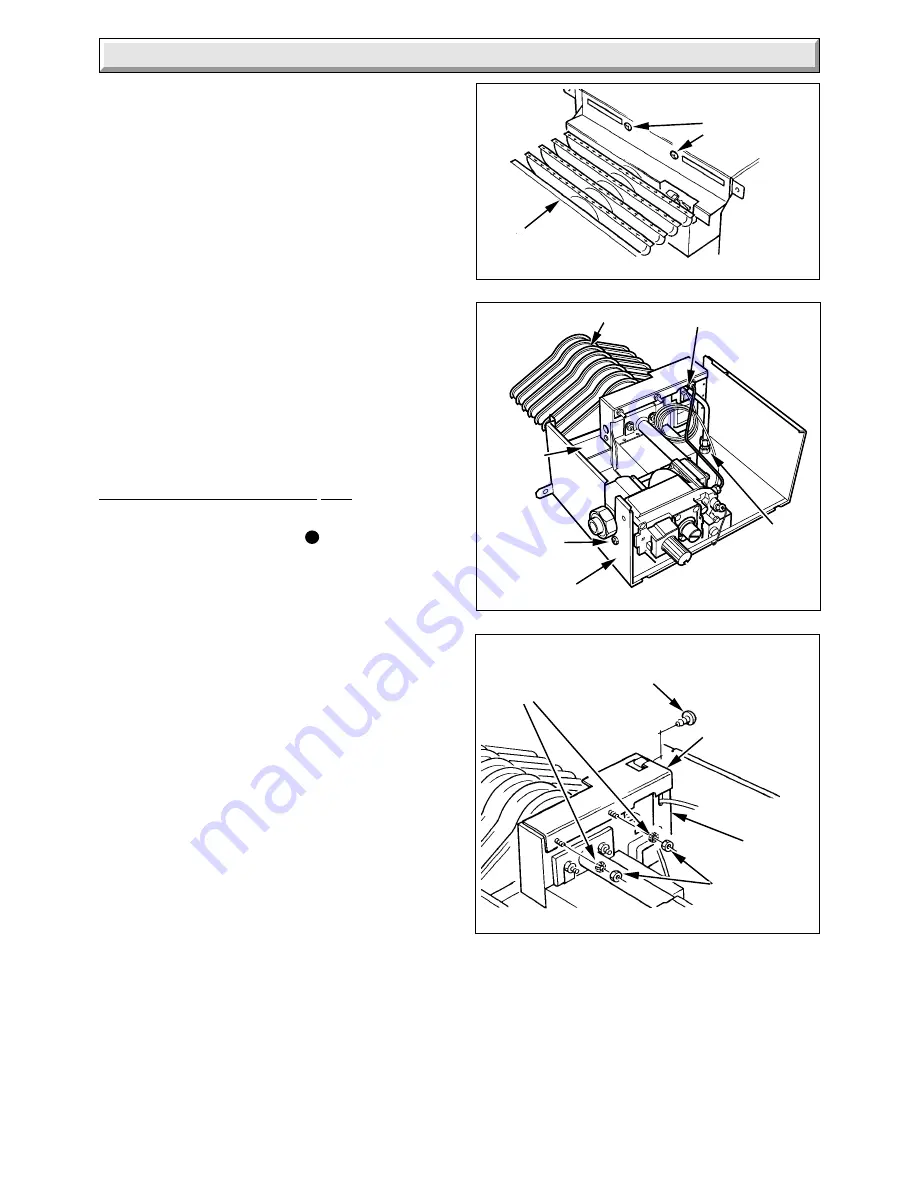
Glow-worm 44 315 40 Installation And Servicing Instructions Download Page 15

15

221781A

Diagram 8.2

Diagram 8.1

SECURING
SCREWS

1613

BURNER

ELECTRODE

BURNER

LOWER

SENSING

TUBE NUT

GAS VALVE
SECURING
SCREW (2)

COMBUSTION
CHAMBER
EXTENSION

BURNER
SUPPORT

8.1 Servicing Notes.

(a) To ensure the continued efficient and safe operation of the
appliance it is recommended that it is checked and serviced as
necessary at regular intervals.

The frequency of the servicing will depend upon the particular
installation conditions and usage, but in general once a year
should be enough.

(b) It is the Law that servicing must be carried out by a
competent person.

(c) Remove the fire front.

(d) Refer to the Gas Fire Front Installation and Servicing
Instructions for full details of fire front removal.

(e) After completing any servicing always test for gas soundness
with a suitable leak detection fluid and carry out functional
check on controls.

(f) Unless stated otherwise reassembly of all components is in
the reverse order to that for removal.

(g) The flue blockage safety device MUST NOT be adjusted or
disconnected. If replacing use only the correct and approved
parts.

8.2 Isolation of Services

Having removed the fire front.

Isolate the electrical supply to the back boiler.

Refer to diagram 6.1 to identify the controls.

Turn the gas valve control knob “A” to 

  “Off” position and turn

the appliance gas service cock to “Fire and Back Boiler Off”, see
diagram 6.2.

8.3 Controls Assembly and Burner.

Disconnect the union at the gas service cock, see   diagram 6.2.

If necessary release the control thermostat capillary and the
mains cable from the clips on the combustion chamber extension,
see diagram 5.1.

Disconnect the electrical plug from the gas valve, see diagram
5.2.

Remove the control box securing screw and lift the box upwards
to release, see diagram 5.2.

Disconnect the ignition lead from the piezo unit and remove
from control box, see diagram 9.1.

Temporarily refit control box.

Note: On reconnecting the ignition lead to the piezo unit, it may
necessary to temporally remove the control thermostat, see
Section 9.8.  Ensure that the control thermostat capillary is
replaced back in the cutout of the control box, see diagram 5.2.

Undo union nut and disconnect the back boiler lower sensing
tube, undo the four combustion chamber extension securing
screws and slide the extension/burner assembly forward to
remove, see diagram 4.8.

Undo the two screws shown in diagram 8.1, which locate the
burner support to the combustion chamber extension.

Turn the combustion chamber extension/burner assembly
upside down.

Undo the lower sensing tube nut, see diagram 8.2.

Disconnect the ignition lead from the piezo unit.

Undo the two screws shown in diagram 8.2 which locate the gas
valve control to the combustion chamber extension.

8   Servicing

Diagram 8.3

SHAKEPROOF
WASHERS

PILOT SHIELD
MOUNTING
BRACKET

PILOT
SHIELD

NUTS

SCREW

1615

8017

The complete gas carrying assembly can now be lifted clear of
the combustion chamber extension.

Undo the screws on the side of the pilot shield, also the two nuts,
also remove the two shakeproof washers securing the pilot
shield mounting bracket to the burner, see diagram 8.3.  Remove
the pilot shield mounting bracket from the studs on the burner
and remove the pilot shield.

Inspect the pilot for damage or blockage, clean or replace flue
blockage safety device as necessary.

Make sure the spark gap is as diagram 8.4.

Summary of Contents for 44 315 40

Page 1: ...To be left with the user Customer Services Tel 01773 828100 Fax 01773 828070 8010 References in these instructions to British Standards and Statutory Regulations Requirements apply only to the United Kingdom For Ireland the rules in force must be used This is a Cat I 2H Appliance BS 6332 BS 5258 For use with specially designed Glow worm fire fronts only Glow worm 56 2 Back Boiler Unit GC No 44 315...

Page 2: ...sh Standards Where no British Standard exists materials and equipment should be fit for their purpose and of suitable quality and workmanship Sheet Metal Parts WARNING When installing or servicing this back boiler care should be taken when handling the edges of sheet metal parts to avoid any possibility of personal injury 1 1 Statutory Requirements The installation of this back boiler unit must be...

Page 3: ...o the back boiler For all types of installation a standard sized builder s opening is required see diagram 1 2 It is important that the opening is cleared of debris and mortar It is recommended that the access hole for pipework into the fireplace or builder s opening is either at the left hand or right hand side of the chimney breast If access is required at both sides then it may be necessary to ...

Page 4: ...f BS5422 It is also recommended that a frost protection thermostat is fitted 1 10 Draining Tap Adraining tapmustbeprovidedatthelowestpointofthe system which will allow the entire system the back boiler and hot water cylinder to be drained Draining taps shall be to the current issue of BS2879 1 11 Safety Valve A safety valve need not be fitted to an open vented system 1 12 Back Boiler Location This...

Page 5: ...ensions of a hearth see diagram 2 1 2 2 Combustible Hearth If the hearth is existing and made of a combustible material the back boiler must be installed to the dimensions in diagram 2 2 2 3 With Surround The combined thickness of the surround and lintel must be checked to make sure that the back boiler can be positioned within the opening to allow easy connection of the flue into the back boiler ...

Page 6: ...oubt seek advice from the local gas undertaking or Hepworth Heating Ltd 3 2 Existing Chimney An existing brick chimney must be thoroughly swept and all debris cleared away before lining Removeanyregisterplates dampersandthelike Alternatively it may be locked in the open position A flexible flue liner is preferred but a rigid liner may be used with connection to the back boiler flue socket made wit...

Page 7: ...e side of the heat exchanger see diagram 1 1 4 3 Pumped Heating with Gravity Domestic Hot Water All pipework must comply with the current issue of BS5546 The domestic hot water flow and return pipes must be 28mm The domestic return must be into the connection directly below the domestic flow connection Refer to diagram 1 3 for a diagrammatic layout If it is necessary to route pipework from both si...

Page 8: ... is positioned on the combustion chamber such that the flow pipe exits on the same side as the back boiler connections It is recommended that the pumped return is prepiped as in diagram 4 3 If the heat exchanger connections are opposite hand to that required turn in the same manner as described in Section 4 3 paragraph 7 4 5 Pump Isolating valves integral if possible must be fitted each side of th...

Page 9: ...self tapping screw provided into the rear of the flue socket as in diagram 4 7 Reposition the back boiler into the builder s opening and secure to the prepared base with the screws provided Connect the system pipework to the back boiler unit preplumbed pipework Refitthecombustionchamberextension ifpreviouslyremoved Connect gas supply to gas service cock Leave gas service cock in the Back Boiler Fi...

Page 10: ...ly cable coming from the left hand side of the builder s opening If however it must come from the right hand side it must be secured under the front edge of the combustion chamber extension using the two cable clips from the fittings pack as shown in diagram 5 1 Make sure that all cables are routed well clear of hot surfaces 5 2 Access to the Boiler Control Box Disconnectthegasvalveelectricalplug ...

Page 11: ...ng sure that the control thermostat capillary is positioned so that it passes through the cutout in the control box panel see diagram 5 2 Secure with screw previously removed see diagram 5 2 Refit the gas valve electrical plug 5 6 Control Thermostat Phial Unwind the capillary so that it will be well clear of any part of the back boiler which becomes hot and insert it fully into the pocket see diag...

Page 12: ...ff that is fully anti clockwise Make sure the control thermostat phial is correctly located see Section 5 6 Remove the back boiler burner pressure test screw G and connect a suitable pressure gauge If flue blockage safety device sensing tube is not fitted remove the plastic ferrule from the bulkhead connector on the air duct replace ferrule after testing commissioning Turn gas service cock K to Ba...

Page 13: ...lows With the main burner alight slightly push in gas valve control knob A and then turn it fully clockwise until is against the setting point This will cause the main and pilot burner to go out Note relighting will not now be possible as the safety device in the gas valve has been activated Check that the flame failure device closes within 60 seconds indicated by a click from the valve DONOTATTEM...

Page 14: ...t of the heating system being out of use during frost and freezing conditions Reminder leave these instructions with the user Advise the user that the Benchmark logbook should be completed by the installation engineer on completion of commissioning or servicing 5197 6 Commissioning Diagram 6 3 Diagram 6 4 20mm FLAME DIMENSION Pilot Shield omitted for clarity 5340 0 10 20 30 40 50 60 70 80 90 5 10 ...

Page 15: ...amberextension see diagram 5 1 Disconnect the electrical plug from the gas valve see diagram 5 2 Removethecontrolboxsecuringscrewandlifttheboxupwards to release see diagram 5 2 Disconnect the ignition lead from the piezo unit and remove from control box see diagram 9 1 Temporarily refit control box Note On reconnecting the ignition lead to the piezo unit it may necessary to temporally remove the c...

Page 16: ...nd thermocouplebeforereplacingthepilotshieldmountingbracket see diagram 8 3 Loosely replace the gas valve control securing screws see diagram 8 2 Refit the two screws shown in diagram 8 1 which locatetheburnersupporttothecombustionchamberextension Refit the lower sensing tube nut into the bulkhead connection Then fully tighten the gas valve securing screws Before replacing the burner and controls ...

Page 17: ...of removal c After replacing any gas carrying parts always test for gas soundness using a suitable leak detection fluid Also carryout functional check of controls d Refer to the Gas Fire Front Installation Instructions for details of the removal of the fire front e Isolate the electrical supply to the back boiler f Remove the gas fire front plinth g Refer to diagram 6 1 to identify the back boiler...

Page 18: ...diagram 8 2 Transfer the union nut and liner to the replacement gas valve using a small amount of approved jointing compound on the external thread only When fitting the thermocouple only tighten the nut at the gas valve a quarter turn beyond finger tight 9 4 Ignition Lead Gain access as the relevant parts of Section 8 3 Remove the lead from the electrode and piezo unit Fit the silicone sleeve ove...

Page 19: ...minium foil gasket see diagram 9 3 Ensure no air bubbles are trapped underneath the foil Important Make sure that the mica window fully covers the opening and that the hole in the aluminium foil gasket is centred over opening 9 10 Flue Blockage Safety Device Sensing Tube Fitting Removefilter unscrewthreadcuttingscrewandremovesensing tube fitting assembly see diagram 9 4 When fitting new filter tak...

Page 20: ...ug ensuring no short circuits mains voltage Turn on power supply and measure voltage Is the voltage between 216 and 264 volts Check control box wiring Isolate the power supply to the control box Reconnect gas valve Turn on power supply Does main burner light Turn off boiler thermostat measure voltage across 3 and 4 Is the voltage zero Does the main burner extinguish Boiler electrical system operat...

Page 21: ...afety device sensing filter is clean if not remove clean and replace NO YES Hold down control knob on gas valve Ignite pilot burner and allow thermocouple to attain operating temperature Measure the OPEN CIRCUIT voltage Is voltage greater than 15mV Faulty thermocouple Replace Note the open circuit reading then measure the CLOSED CIRCUIT voltage Note this voltage Referring to the diagnosis graph ma...

Page 22: ...ay alight when gas valve knob is released PILOT SATISFACTORY Does pilot flame envelop thermocouple Replace faulty flue blockage safety device Check thermocouple circuit using Thermocouple fault finding see diagram 10 3 On pressing piezo unit button is there a spark across electrode gap Pull ignition lead off electrode Hold end of lead close to pilot burner and operate piezo unit Is there a spark a...

Page 23: ...ring 334 658 10 208680 Sensing tube filter Diagram 11 1 11 Spare Parts 9 5 4 7 2 3 8 6 1 8034 10 When spare parts are required apply to your local supplier Please quote the name of the appliance Glow worm 56 2 BBU also the serial number of the back boiler to be found on the data label on the combustion chamber extension see diagram 6 1 If ordering from British Gas the GC number should also be quot...

Page 24: ...l only if the material is broken Normal handling should not cause discomfort but follow normal good hygiene and wash your hands before eating drinking or going to the lavatory If you do suffer irritation to the eyes or severe irritation to the skin seek medical attention THERMOSTATS These contain very small amounts of xylene in the sealed phial and capillary If broken under normal circumstances th...

Reviews: