background image

35

10  Twin Flue - Length, Preparation and Installation

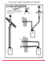
Diagram 10.31

12985

Installation Details

The parts available for a twin flue system installation are 

shown in diagram 10.30.

Boiler Connection

IMPORTANT

: The flue seals are sensitive to mineral oil based 

lubricants. 

Do not grease the seals

. If the seals do need to 

be lubricated 

use


only water

Remove the top flue outlet cover complete with resonator and 

discard, see diagram 10.4.

Place the twin flue adaptor onto the outlet of the boiler with 

the air inlet to the left hand side, see diagram 10.31. Secure 

the adaptor to the top panel with the screws provided. Care 

should be taken when inserting the screw through the hole in 

adaptor top.

Air and Flue Pipe Installation

The air and flue pipes can now be built up from the boiler.

The flue must be designed with a continuous fall towards the 

boiler. If using the horizontal flue pipe or 90° bends the pipe 

must be inclined at 44mm/metre (2.5°)


minimum, see diagram 

10.29.

Alternatively if space allows, use 45° bends in place of 90º 

bends.

To aviod rain ingress to the air Inlet terminal, it is good 

practice to aim the inlet downwards by approx 2° as rain can 

damage the boiler. The Flue outlet pipe must always run at 

44mm/metre (2.5°) back to the boiler.

IMPORTANT

:-

Long lengths of flues must be secured to the wall or ceiling it 

runs against. Use at least one fixing bracket on each flue joint 

used or on straight flue runs every joint and for every metre 

flue run.

Provision must be made in concealed boxing or ductwork that 

the flue joints can be inspected during annual servicing.

The flue seals are sensitive to mineral oil based lubricants. 

Do 

not grease the seals

. If the seals do need to be lubricated 

use


only water

Do not use the flue pipe to attach other pipes or equipment. If 

visible, advise the householder not to hang or clip items to flue 

pipes.

Do not stress the flue connections during the installation, this 

can damage the flue seals.

Horizontal Terminal Installation

NOTE:

 The air inlet terminal and the flue outlet terminals 

must never be installed on the opposite sides of a property. 

Termination must only be on the same wall or adjacent walls. 

When installed close together separated vertically, the air 

inlet must be fitted below the flue outlet terminal (see diagram 

10.29). 

With due consideration to terminal clearances mentioned in 

section 4.2 drill the one or two holes as required with a 90mm 

core drill.

Push the horizontal terminal through the wall allowing approx. 

100mm to protrude outside.

Push a grey rubber wall seal onto either side of the wall 

ensuring that both wall seals are pushed up to the wall 

surface, see examples (b) and (c) diagram 10.29.

Vertical Terminal Installation

With due consideration to terminal clearances mentioned in 

Section 4.2, project the rise of the flue pipe to roof level and 

cut 150mm hole in the roof.

(a) Pitched Roof

Fit the required pitched roof weather collar over the 150mm 

hole in the roof. Make good the tiling or slating around the 

collar incorporating the flashing of the weather collar. Position 

the angle cap over the weather collar in the correct orientation 

to attain the correct angle for your roof. One way round gives 

a pitch of 25°-38° and the other gives 37°- 50°.

(b) Flat Roof

Fit the aluminium weather collar over the 150mm hole in the 

roof ensuring a weather tight seal. 

Horizontal Pipes-Completion of Installation

Having built the pipe(s) from the boiler to the terminal(s), the 

length of the final pipe piece can be determined. Cut pipes at 

the opposite end to the ‘O’ ring seal making square and free 

from burrs. Push the horizontal terminal through the wall to 

engage the final pipe piece and pull back ensuring  the grey 

wall seals are fully pulled up to the outside and inside wall 

faces.

Vertical Pipes-Completion of Installation

Refer to diagram 10.29.

For installation of (a), attach the twin pipe to concentric 

flue adaptor, part number A2011600, to the base of vertical 

terminal assembly. For installation of (b), attach the single 

pipe to concentric adaptor, part number A2011500, to the base 

of vertical terminal assembly.

With the vertical terminal assembly positioned in the roof, 

the length of the final pipe can be determined. Cut the flue 

to the desired length measuring from the ‘O’ ring seal end 

and discard the plain end of the tube. The cut end should 

be square and free from burrs. Carefully push the terminal 

assembly upwards to allow room for fitting the final flue 

piece(s). Fit a 100mm fixing bracket to the terminal assembly 

Part No2000460486. Pull the terminal assembly down and 

join to the flue system. Ensure that the terminal is making a 

weather tight seal on the weather collar. Secure the fixing 

bracket fitted to the terminal to the roofing struts or a purpose 

made batton.

Summary of Contents for 24cx

Page 1: ...www glow worm co uk Installation and Servicing High Efficiency Condensing Combination Boilers Flexicom 30cx G C No 47 047 34 24cx G C No 47 047 33 35cx G C No 47 047 35 12801 ...

Page 2: ...r guarantee registration card If your guarantee registration card is missing you can obtain a copy or record your registration by telephoning the Glow worm Customer Service number 01773 828100 Guarantee Registration Customer Service 01773 828100 Technical Helpline 01773 828300 General and Sales enquiries Tel 01773 824639 Fax 01773 820569 To register your Glow worm appliance call 0800 0732142 Bench...

Page 3: ...17 Boiler Fixing 8 18 Safety Discharge Valve and Condensate Connections 9 19 Flue Length Preparation and Installation 10 21 Electrical Connection 11 37 Commissioning 12 38 Servicing 13 42 Fault Finding 14 47 Replacement of Parts 15 53 Spare Parts 16 61 Manual Handling 17 62 Declaration of Conformity 18 63 INTRODUCTION INSTALLATION MAINTENANCE These instructions consist of Installation Servicing Fa...

Page 4: ...n accordance with the relevant standards In GB this is BS 7671 In IE this is the current edition of ETCI rules The boiler MUST be connected to a permanent 230V ac 50Hz supply Connection of the whole electrical system of the boiler including any heating controls to the electrical supply MUST be through one common isolator and must be fused 3 Amp maximum Isolation should be by a double pole switched...

Page 5: ...s Where no specific instructions are given reference should be made to the relevant British Standard Code of Practice In IE the installation must be carried out by a competent person approved at the time by the Health and Safety Executive and installed in accordance with the current edition of I S 813 Domestic Gas Installations the current Building Regulations and reference should be made to the c...

Page 6: ... minutes or at any time if the temperature drops to 5 C The burner will switch off when the temperature reaches 35 C Condensate Drain Blockage As a safety feature the boiler will stop working if the condensate drain becomes blocked During freezing conditions an ice blockage in the condense drain external to the house would also activate the safety feature Use warm cloths on the pipe to release an ...

Page 7: ...0 5bar 7 3Ibf in2 0 5bar 7 3Ibf in2 Electrical supply 230V 50Hz fused 3A 230V 50Hz fused 3A 230V 50Hz fused 3A Electrical rating 180W fused 3A 180W fused 3A 180W fused 3A EN437 IP clasification IPX4D IPX4D IPX4D Internal fuse rating on main PCB 2A 2A 2A Gas supply governed meter only and Cat G20 natural gas G20 natural gas G20 natural gas Gas Category I2H I2H I2H Inlet gas working pressure 20mbar ...

Page 8: ... Boiler Dimensions and Hydraulic Schematic All dimensions are given in millimetres except as noted The general arrangment of the boiler is shown in diagram 2 1 and the hydraulic and gas schematic diagram 2 2 The data label is positioned on the front of the inner casing panel 13893 ...

Page 9: ...ot practicable consideration should be given for the space required to insert the flue internally which may necessitate clearance larger than those specified in diagram 3 1 3 3 Timber Frame Buildings If the boiler is to be installed in a timber frame building it should be fitted in accordance with the Institute of Gas Engineers document IGE UP 7 1998 If in doubt seek advice from local gas undertak...

Page 10: ...or use with Part No A2043400 and Part No A2043600 Section 10 page 36 Vertical Flue Vertical Flue Adapter concentric flue Ø60 100 Part No A2024600 Section 10 page 31 Vertical flue terminal kit concentric flue Ø60 100 Part No 2000460480 Section 10 page 31 Direct rear telescopic flue Ø60 100 Part No A2043500 Section 10 page 29 Ridge Tile Terminal Part No A2043800 Section 10 page 30 Multiple Boiler Ch...

Page 11: ...passage of air across it at all times Being a condensing boiler some pluming may occur from the flue outlet This should be taken into consideration when selecting the position for the terminal Carports or similar extensions of a roof only or a roof and one wall require special consideration with respect to any openings doors vents or windows under the roof Care is required to protect the roof if m...

Page 12: ...tion Table and section 12 6 5 6 Filling the Sealed System The boiler is supplied with a filling device see diagram 5 4 This filling device is designed to enable the filling and pressurisation of the system in the event of loss of pressure NOTE The water pressure at the boiler must be at least 1 2bar to enable filling the boiler to a minimum pressure If not pressurisation must be carried out by an ...

Page 13: ...13 5 Water System Heating Diagram 5 3 13102 Diagram 5 4 13925 13072 Diagram 5 2 ...

Page 14: ...limited by the boiler control system to minimise scale formation within the hot water pipework However in areas where the water is hard i e more than 200mg litre it is recommended that the hot water setting is reduced and that a scale reducer is fitted refer to the manufacturer s instructions or consult the local water company for additional advice 5 11 Domestic Water Flow Rate The water flow rate...

Page 15: ...15 H H Boiler Securing Screw 6 Installation Preparation Diagram 6 1 12778 ...

Page 16: ...rilling the flue hole 6 4 Flue Hole Cutting External access flue installation can use a 105mm diameter core drill Internal access only flue installation will need a 125mm diameter core drill NOTE The flue is designed with an internal fall of 44mm metre 2 5 therefore the hole can be drilled horizontally If flue extension pipes are to be used then a core drill size of 125mm is required This will all...

Page 17: ...into the wall Assemble the pipes to the jig as shown in diagram 7 1 Fit O ring seal to the Double Check Valve assembly Fit the Central Heating Isolation Valve handles and secure with screws provided Fit the assembled Jig Plate to the Support Plate as shown in diagram 7 2 Assemble the Gas service isolation valve and position onto the plastic plug Plumb system pipe work to the copper tails Do not su...

Page 18: ...The appliance and jig pre filled may contain a small amount of water place a water container beneath the boiler connections Make sure the isolation valves are closed before disconnecting the blanking plugs and discarding the jig plate Position the sealing washers supplied in the Loose Items pack as shown in diagram 6 1 Lifting the boiler into position lean the top of the boiler slightly to the wal...

Page 19: ...uld be used to couple the condensate trap and siphonic drain to a 22mm to 25mm O D non corrosive plastic pipe overflow pipe see diagram 8 2 IMPORTANT Please remove the bung from the flexible pipe before fitting to a drain outlet pipe NOTE the pipe should have a fall of a least 2 5o 44mm metre away from the boiler Condensate should if possible be discharged into the household internal drainage syst...

Page 20: ...20 9 Safety Discharge Valve and Condensate Connections Diagram 9 2 13000 ...

Page 21: ... face is not practicable 13934 10 Telescopic Flue Length Preparation and Installation Multiple Boiler Chimney Flue Length The flue length must be calculated and installed according to the relevant standards EN 13384 1 and 2 C43 flue systems only with reference to the table below and the manufacturers instructions supplied The appliance maximum flue length must be included when calculating the over...

Page 22: ...22 14826 Diagram 10 3 15418 10 Telescopic Flue Length Preparation and Installation Diagram 10 2 ...

Page 23: ...e it can project to a maximum of 600mm refer to diagram 10 6 If this is not desirable then a Standard flue MUST be used and cut to length 10 4 SIDE Flue Remove the top flue outlet cover complete with resonator and discard see diagram 10 4 Using these screws inserted into the same holes on the boiler temporarily secure the flue elbow measure the distance from the outside wall to the butt joint see ...

Page 24: ...0 8 Fit the sealing collar onto the locating ring on the flue terminal see diagram 10 9 With the flue elbow removed push the flue assembly into the wall externally or internally until the end of the assembly protrudes a short way from the inside face of the wall This will enable the internal trim ring if required to be positioned and allow the flue assembly to be drawn back up to the flue elbow Se...

Page 25: ...om inside the building when access to the outside wall face is not practicable Multiple Boiler Chimney Flue Length The flue length must be calculated and installed according to the relevant standards EN 13384 1 and 2 C43 flue systems only with reference to the table below and the manufacturers instructions supplied The appliance maximum flue length must be included when calculating the overall des...

Page 26: ...26 Diagram 10 12 13222 15418 10 Standard Flue Length Preparation and Installation Diagram 10 13 ...

Page 27: ...flue can project to a maximum of 600mm refer to diagram 10 15 10 9 SIDE Flue Remove the top flue outlet cover complete with resonator and discard see diagram 10 4 Using these screws inserted into the same holes on the boiler temporarily secure the flue elbow measure the distance from the outside wall to the butt joint see diagram 10 16 If the measurement Y exceeds 665mm then the appropriate length...

Page 28: ...he opposite end to the terminal The plastic flue duct MUST be cut at the opposite end to the terminal catch The plastic flue duct extensions MUST be cut at the opposite end to seal Insert the flue duct into the air duct terminal assembly remembering to engage the catch within the terminal Fit the sealing collar behind the locating lugs on the flue terminal see diagram 10 18 Push the flue assembly ...

Page 29: ...telescopic terminal assembly into the clamping band grips The telescopic terminal assembly must be pulled forward of the clamping band grips by the dimension shown in diagram 10 21 to ensure a good seal when the boiler is located onto the fixing plate Ensure the correct alignment of the terminal There are two alternative methods of securing the flue Method 1 There are six holes provided in the cla...

Page 30: ...ht flue length is 8 metres plus the terminal for each 87 5º or 2x45º bends fitted the maximum length must be reduced by 1 metre see diagram 10 22 NOTE 2x45º bends can replace 1x87 5º bend if necessary When using 87 5º bends any horizontal extension pipe should be inclined by a minimum of 44mm metre 2 5º towards the boiler to facilitate condense removal see a in diagram 10 22 Alternatively use 45º ...

Page 31: ...int then tighten the two screws on the securing collar see diagram 10 26 Fit more extension pipes as required using the collar and screws supplied with each extension pipe To fit position the collar centrally over the joint tighten the two screws on the securing collar Using the holes provided in the securing collar drill and insert the two self tapping srews supplied see diagram 10 27 The rubber ...

Page 32: ...ng end and discard the plain end of the tube The cuts must be square and made free of burrs to allow correct assembly NOTE The flue pipe is 10mm longer than the air pipe see diagram 10 28 Carefully push the terminal assembly upwards to allow room for fitting the final flue piece Fit a fixing bracket to the terminal assembly Pull the terminal assembly down and join to the flue system Ensure that th...

Page 33: ...win Flue Length Preparation and Installation Diagram 10 29 15406 Secure long flue lengths horizontal vertical to walls or ceiling at every joint or on straight flue runs at every joint and every metre flue run ...

Page 34: ...ed by a minimum of 44mm metre 2 5º towards the boiler to facilitate condense removal Alternatively use 45º bends to avoid horizontal runs in the flue pipe Multiple Boiler Chimney Flue Length The flue length must be calculated and installed according to the relevant standards EN 13384 1 and 2 C43 flue systems only with reference to the table below and the manufacturers instructions supplied The app...

Page 35: ...agram 10 29 With due consideration to terminal clearances mentioned in section 4 2 drill the one or two holes as required with a 90mm core drill Push the horizontal terminal through the wall allowing approx 100mm to protrude outside Push a grey rubber wall seal onto either side of the wall ensuring that both wall seals are pushed up to the wall surface see examples b and c diagram 10 29 Vertical T...

Page 36: ... contact Glow worm refer to page 2 The Plume Management Kit is supplied with installation instructions Refer to BS5546 or BS6798 for advice on disposal of boiler condensate 12997 Diagram 10 32 10 Deflector Flue Terminal Kit Diagram 10 33 14465 10 17 Deflector Flue Terminal Kit The terminal kit fits onto the telescopic and standard horizontal flue see diagram 4 1 for kit contents The kit is also su...

Page 37: ...ng Remove the electrical cartridge from the fittings pack Remove the securing screw to open the cartridge NOTE There are two screws supplied loose in the electrical cartridge these will be required to secure the cartridge into the electrical interface housing Slacken the screws of the cable strain relief in the electrical cartridge see diagram 11 1 Route the mains supply and system cables through ...

Page 38: ...g Refer to diagram 12 1 1 Ensure that the flexible hose is connected to the double check valve by tightening the knurled nut marked E 2 Ensure that the water isolation valves are securely tightened onto the jig blanking plugs 3 Open the Central Heating Flow and Return isolation valves marked A using a screwdriver or a 4mm allen key slot in line with the axis of the isolation valves shown closed in...

Page 39: ...l the heating system to a pressure of 1 0bar Close the two filling taps 6 Vent all air from the system repeat step 5 as neccessary until the system is full and all the air has been removed 7 Close the Domestic Cold Water isolation valve marked B using a screwdriver or a 3mm allen key shown closed in diagram 8 Close the Central Heating Flow and Return isolation valves marked A using a screwdriver o...

Page 40: ...using the MODE and plus SELECTOR buttons The appliance will then continue to operate in central heating until the user controls are satisfied or there is another demand made for hot water 12 Commissioning 12 7 Check the Gas Inlet Pressure Gas Rate The supply from the governed meter must be of adequate size to provide a steady inlet working pressure of 20mbar 8in wg at the boiler On completion test...

Page 41: ...iler Advise the user of the precautions necessary to prevent damage to the system boiler and the building in the event of the heating system being out of use during frost or freezing conditions Advise the user that the permanent mains electrical supply SHOULD NOT be switched off as the built in frost protection and pump saver program will not operate Advise the User if the mains electricity and ga...

Page 42: ...of the results The flue gas analyser used should be one meeting the requirements of BS7927 or BS EN50379 3 and be calibrated in accordance with the analyser manufacturers requirements Competence can be demonstrated by satisfactory completion of the CPA1 ACS assessment which covers the use of electronic portable combustion gas analysers in accordance with BS 7967 parts 1 to 4 Ensure that the gas an...

Page 43: ...e the offset adjustment anti clockwise to decrease to the required CO2 refer to diagram 13 4 and the SETTING column in the table Exit the minimum rate function press the mode and buttons simultaneously this will reset the boiler to the default display 3 Re Check CO2 and check the CO CO2 combustion ratio Re check the maximum and minimum CO2 values to ensure that they are within the setting limits i...

Page 44: ...he fan retaining bracket To ease removal of the securing nut from the fan retaining bracket a flat bladed screwdriver can be used in the position shown and gently levered down as indicated see diagram 13 10 Remove the fan and gas valve assembly The silencer rear is a push fit so no tools are required for its removal or fitting see diagram 13 9 Check the spark electrode gap is 4mm Clean and adjust ...

Page 45: ...14288 Diagram 13 10 14081 Diagram 13 9 14409 GAS VALVE GAS PIPE ELECTRICAL CONNECTION removed SECURING SCREW 3 TUBING NUT Diagram 13 7 14079 Diagram 13 8 13128 SECURING NUT SUPPORT BRACKET IGNITION LEAD SPADE CONNECTOR IGNITER UNIT EARTH CONNECTION ELECTRICAL CONNECTIONS ...

Page 46: ...his component Check the condition of the seal and replace if worn or damaged To replace remove the old seal and thoroughly clean the casing surfaces Fit the new seals these are supplied to the correct lengths and are in four pieces for use on the sides top and bottom 13 7 Service Completion Re check the combustion as described at the beginning of this section On completion of the service the Bench...

Page 47: ...lve refer to section 12 7 Check that the heating system pressure indicates at least 1mb if not fill and vent the system as described in section 12 2 Check that all external controls are on Check the functional flow diagram 14 5 14 2 Fault Codes Fault codes take priority over all other display functions in the event of a fault occuring refer to diagram 14 6 If multiple faults occur the codes will b...

Page 48: ...48 14 Fault Finding 14516 Diagram 14 4 MODE ...

Page 49: ...49 13012 Diagram 14 5 CENTRAL HEATING DHW 13015 14 Fault Finding ...

Page 50: ...50 14 Fault Finding 14027 Diagram 14 6 FAULT CODES ...

Page 51: ...mer mode Check CH setpoint Check external controls S 32 Antifreeze active fan speed variation too high Check fan connection waiting during blocking function S 34 frost protection active Priority 4 Temperature below 8O C check thermistor connection if this is not true S 36 No Heating demand from external controls 24V Check wiring in external controller Check wiring at Installer Interface S 42 Acces...

Page 52: ...ve level 1 access the number indicates the diagnostic number below Use the and to cycle through the selections below To select a diagnostic number press the MODE button when the correct number is selected The display will show the parameter value of the diagnostic number selected To return to the diagnostic number selector simply press the MODE button To change the parameter use the or buttons Onc...

Page 53: ...d remove the four screws securing each side panel to the boiler two below and two at the top Draining of Boiler Heating Circuit Drain down the Heating Circuit of the boiler only by closing the heating flow and return isolating valves on the wall mounting jig Attach a length of hose to the drain point and open the drain valve see diagram 15 1 After replacing parts close the drain valve and remove t...

Page 54: ...trical connections see diagram 13 7 Remove the securing nut holding the fan retaining bracket press down on burner to ease removal of securing nut Slide out the fan retaining bracket Lift front of bracket away from stud and pull forward to release the fan see diagram 13 10 Lift fan gas valve assembly up and forward away from locating studs Remove fan gasket and replace if necessary To replace the ...

Page 55: ...Refer to diagram 15 4 Remove the electrical connections from the thermistor Remove the retaining clip from the return pipe Remove the thermistor from the retaining clip Note that the polarity of the wiring to thermistor is unimportant Note that the polarity of the wiring to thermistor is unimportant 15 18 Domestic Hot Water Thermistor For access refer to section 15 1 Refer to diagram 15 5 Remove t...

Page 56: ...scharge Valve For access refer to section 15 1 Refer to section 15 1 and drain the boiler heating circuit Refer to diagram 15 8 Undo the safety discharge valve union and remove from the pipework Remove the retaining clip and withdraw the safety discharge valve Fit new O ring Refill vent and pressurise the boiler and check for leaks 15 22 Automatic Air Vent For access refer to section 15 1 Refer to...

Page 57: ...r open the cold water isolation valve and slowly open a hot water tap to remove air Close the hot water tap and check for any leaks 15 24 Three Way Valve For access refer to section 15 1 Refer to section 15 1 and drain the boiler heating circuit and the boiler hot water circuit Refer to diagram 15 11 Undo the nut retaining the heating return isolation valve to the fixing jig Be careful not to lose...

Page 58: ...nections Remove the fan and gas valve assembly Remove the condensate trap Remove the drain outlet pipe from the base of the trap see diagram 15 1 Remove the condensate drain securing screw and carefully pull the trap forward see diagram 13 13 Remove the heat exchanger Remove the retaining clip see diagram 15 12 which secures the flow pipe brass elbow into the hydroblock Remove the retaining clip w...

Page 59: ...en re fitting the burner see diagram 15 15 NOTE Fit all replacement gaskets and seals when re fitting parts Filling the boiler heating circuit domestic hot water system and re pressurising After replacing parts open the cold water isolation valve and slowly open a hot water tap to remove air Close the hot water tap and check for any leaks After replacing parts close the drain valve and remove the ...

Page 60: ...s as you push down and clip back into place 15 27 Control Box For access refer to section 15 1 Hinge down the control box and unclip the rear cover to gain access Remove relevant electrical connections from main PCB and grommets from the control box IMPORTANT Support the control box whilst undoing the hinges Remove the hinge securing screws accessed from beneath the boiler and remove the control b...

Page 61: ...63 Igniter unit H42773 3 0020020781 Heating flow return thermistor 2 H42792 4 0020014160 DHW thermistor H36325 5 0020020735 Gas valve 24cx 30cx H42724 5 0020059600 Gas valve 35cx H69002 6 0020020731 Electrode H42720 7 0020020728 Burner 24cx 30cx H42718 7 0020059602 Burner 35cx H69008 8 0020023826 User interface H42784 9 0020014402 Plate to plate heat exchanger 24cx H43160 9 0020014402 Plate to pla...

Page 62: ...cks Remove top polystyrene pack with fittings Positioning of Appliance for Final Installation no obstructions Recommend 2 persons lift appliance to position into place Fit bracket securely onto wall before lifting appliance into position Obtain firm grip on front and sides of appliance lift upwards ensure stable bal ance achieved and lift upwards to position in place on bracket Ensure safe lifting...

Page 63: ...63 18 Declaration of Conformity 14505 ...

Page 64: ...igh efficiency info Because of our constant endeavour for improvement details may vary slightly from those shown in these instructions Glow worm Nottingham Road Belper Derbyshire DE56 1JT 0020057798 04 01 10 ...

Reviews: