Glow-worm 18sxi Installation And Servicing Manual Download Page 29

29

10  Vertical Flue - Length, Preparation and Installation
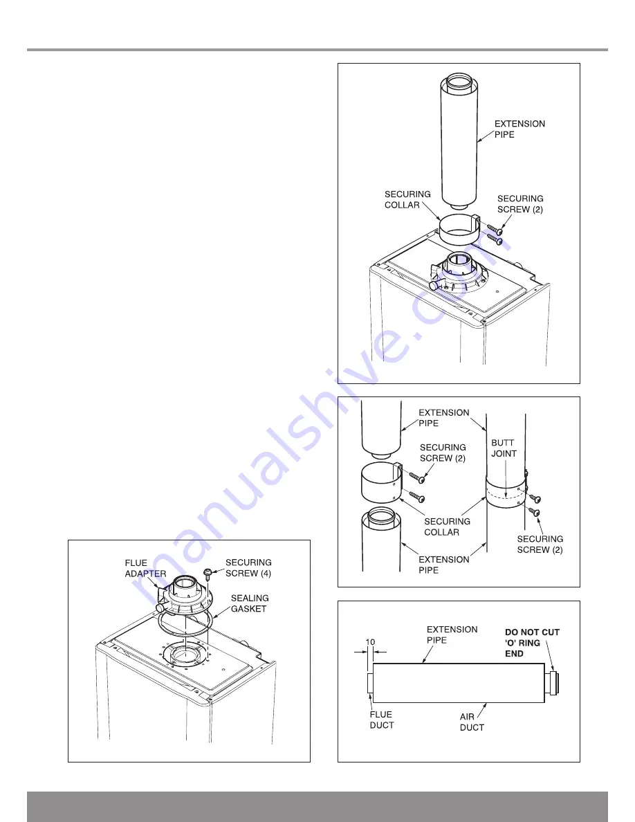
Diagram 10.20

13243

Diagram 10.21

13242

Diagram 10.22

12982

Completion of Installation

With the flue terminal positioned in the roof the length of 
the final pipe can be determined.  If a telescopic length 
cannot be used, then a standard flue length can be cut to 
make the correct length. Cut the flue to the desired length 
measuring from the ‘O’ ring end and discard the plain end of 
the tube. The cuts must be square and made free of burrs 
to allow correct assembly. (NOTE: The flue pipe is 10mm 
longer than the air pipe), see diagram 10.23. Carefully push 
the terminal assembly upwards to allow room for fitting the 
final flue piece. Fit a fixing bracket to the terminal assembly. 
Pull the terminal assembly down and join to the flue system. 
Ensure that the terminal is making a weather tight seal on the 
weather collar. Secure the fixing bracket fitted to the terminal 
to the roofing struts or a purpose made batton.

Diagram 10.23

12983

Summary of Contents for 18sxi

Page 1: ...1 Installation and Servicing High Ef ciency Condensing Combination Boilers Ultracom www glow worm co uk 30sxi G C No 41 019 08 18sxi G C No 41 019 07...

Page 2: ...the boiler having been serviced by a CORGI registered gas installer in accordance with the manufacturer s recommendations We strongly recommend regular servicing of your gas appliance but where the c...

Page 3: ...ety Discharge Valve and Condensate Connections 9 17 Flue Length Preparation and Installation 10 19 Electrical Connection 11 34 Commissioning 12 36 Servicing 13 40 Fault Finding 14 44 Replacement of Pa...

Page 4: ...f the boiler may involve lifting pushing and pulling the use of a sack truck may be required The following handling techniques and precautions should be considered Grip the boiler at its base Be physi...

Page 5: ...instructions are given reference should be made to the relevant British Standard Code of Practice In IE the installation must be carried out by a competent person and installed in accordance with the...

Page 6: ...ch off when the temperature reaches 35O C Condensate Drain Blockage As a safety feature the boiler will stop working if the condensate drain becomes blocked During freezing conditions this may be due...

Page 7: ...bar 7 3Ibf in2 0 5bar 7 3Ibf in2 Electrical supply 230V 50Hz fused 3A 230V 50Hz fused 3A Electrical rating 180W fused 3A 180W fused 3A EN60529 IP clasification IPX4D IPX4D Internal fuse rating on main...

Page 8: ...100 100 140 176 450 726 C BOILER L 334 127 16 130 130 2 1 Boiler Dimensions Hydraulic Schematic All dimensions are given in millimetres except as noted The general arrangment of the boiler is shown in...

Page 9: ...ould be given for the space required to insert the ue internally which may necessitate clearance larger than those speci ed in diagram 3 1 3 3 Timber Frame Buildings If the boiler is to be installed i...

Page 10: ...n Flue Twin Flue Adapter concentric ue 80 Part No A2011000 Section 10 page 31 Plume Management Kit basic set white concentric ue 60 100 Part No A2044100 for use with Part No A2043400 and Part No A2043...

Page 11: ...nimum distances for ue terminal positioning must be those detailed in I S 813 Domestic Gas Installations The terminal must be exposed to the external air allowing free passage of air across it at all...

Page 12: ...the Sealed System Provision for lling the system at low level must be made see diagram 5 2 There must be no permanent connection to the mains water supply even through a non return valve NOTE It is i...

Page 13: ...SE UNION SUPPLY PIPE CONTROL VALVE CONTROL VALVE DOUBLE CHECK VALVE BOILER RETURN FLOW HEATING CIRCUIT DRAIN POINT SUPPLY PIPE AIR GAP TUNDISH CONTROL VALVE CONTROL VALVE TYPE CA BACKFLOW PREVENTION D...

Page 14: ...re line into the corner then 176mm along the adjacent wall see diagram 6 2 For extended side ues the ue hole centre should be determined by extending the dashed inclined line on the template to the si...

Page 15: ...ection 17 Manual Handling Lifting the boiler into position lean the top of the boiler slightly to the wall and position just above the hanging bracket Lower the boiler slowly and engage onto the hangi...

Page 16: ...the valves for locating a spanner to aid tightening to copper tails NOTE Make sure that the test and drain points are accessible refer diagram 8 1 Plumb the system pipe work to the copper tails NOTE D...

Page 17: ...nd should be used to couple the condensate trap and siphonic drain to a 22mm to 25mm O D non corrosive plastic pipe over ow pipe see diagram 9 2 IMPORTANT Please remove the bung from the exible pipe b...

Page 18: ...GTH OF PIPE 3M MAX 25mm MIN SEAL BOTTOM OF TUBE SEALED 100mm PLASTIC TUBE 300mm MIN GROUND either or 500mm MIN HOLE DEPTH 400mm MIN LIMESTONE CHIPPINGS 2 ROWS OF 3 x 12mm HOLES AT 25mm CENTRES 50mm FR...

Page 19: ...run back into the boiler and out via the condensate drain The ue can be installed from inside the building when access to the outside wall face is not practicable Horizontal Telescopic Flue Diagram 1...

Page 20: ...SECURING COLLAR FLUE ELBOW GASKET fitted SEALING TAPE telescopic only A2043600 Top Outlet Horizontal telescopic flue pack SCREW x 1 SCREW x 2 SCREW x 2 SCREW x 4 13221 Diagram 10 3 13765 10 Telescopi...

Page 21: ...OT cut the ue it can project to a maximum of 600mm see diagram 10 5 If this is not desirable then a Standard ue MUST be used and cut to length 10 4 SIDE Flue With the ue elbow temporarily tted measure...

Page 22: ...e ue elbow Secure the ue elbow in position on top of the boiler with four screws supplied Draw the ue assembly from wall and engage the ue duct into the elbow and butt t between the air duct and ue el...

Page 23: ...ensate to run back into the boiler and out via the condensate drain The ue can be installed from inside the building when access to the outside wall face is not practicable 10 Standard Flue Length Pre...

Page 24: ...LBOW GASKET fitted A2043400 Top Outlet Standard Horizontal Concentric Flue Pack STANDARD TERMINAL ASSEMBLY SCREW x 2 SCREW x 2 SCREW x 4 TRIM RING Diagram 10 11 13222 13765 10 Standard Flue Length Pre...

Page 25: ...oject to a maximum of 600mm if this is desirable refer to diagram 10 14 10 9 SIDE Flue With the ue elbow temporarily tted measure the distance from the outside wall to the butt joint see diagram 10 15...

Page 26: ...gs on the ue terminal see diagram 10 17 Push the ue assembly into the wall externally or internally initially until the end of the assembly protrudes a short way from the inside face of the wall This...

Page 27: ...aight ue length is 10 metres plus the terminal for each 90o or 2x45o bends tted the maximum length must be reduced by 1 metre see diagram 10 18 NOTE 2x45 bends can replace 1x90 bend if necessary When...

Page 28: ...collar Using the holes provided in the securing collar drill and insert the two self tapping srews supplied see diagram 10 22 When installing the ue it is recommended that it is supported every 2 met...

Page 29: ...from the O ring end and discard the plain end of the tube The cuts must be square and made free of burrs to allow correct assembly NOTE The ue pipe is 10mm longer than the air pipe see diagram 10 23...

Page 30: ...30 10 Twin Flue Length Preparation and Installation Diagram 10 24 13226...

Page 31: ...e 1x90 bend if necessary The maximum permitted combined air inlet ue outlet ue length is 40 metres plus terminal assemblies for each 90 or 45 x 2 bends tted the maximum length must be reduced by 1 met...

Page 32: ...ut 150mm hole in the roof a Pitched Roof Fit the required pitched roof weather collar over the 150mm hole in the roof Make good the tiling or slating around the collar incorporating the ashing of the...

Page 33: ...d in section 4 2 see diagram 10 27 The maximum length of the Plume Management Kit must NOT exceed 6m with a horizontal concentric ue length of 2m max For each 90o bend or 2 x 45o bends the maximum len...

Page 34: ...d spur box provided that it is not used in a room containing a xed bath or shower The boiler is suitable for installation in bathroom zones 2 and 3 11 1 Electrical Wiring If you are tting the Glow wor...

Page 35: ...CTION PLUG Connect mains supply and system controls as diagram 11 3 External controls should be tted in accordance with the rules in force 11 4 Electrical Cartridge Securing Fit electrical cartridge i...

Page 36: ...ted 12 4 Initial Lighting NOTE If you have tted a Glow worm Options Board Kit please refer to the instructions supplied with the kit for completion of commissioning Do not operate the boiler without w...

Page 37: ...is calling for heat Balance the radiators as required and if tted adjust valve to give the required system differential Turn off all radiators that can be shut off by the user and check to see if less...

Page 38: ...ion 35 which imposes a duty of care on all persons who let out any property containing a gas appliance in the UK The user shall not interfere with or adjust sealed components It is the Law that any se...

Page 39: ...n when Hi is selected will force the boiler to maximum rate the display will ash between Hi and the default display this will indicate the boiler has been forced to maximum 9 Adjust if necessary the b...

Page 40: ...either facility then the appliance MUST be turned off and disconnected until such equipment is available If the gas rate requires adjustment you MUST NOT adjust the gas valve without a gas analyser re...

Page 41: ...m 13 3 13 4 Spark Electrode Disconnect the spark electrode plug and earth lead Remove the two securing screws and withdraw the spark electrode carefully from the combustion chamber see diagram 13 5 In...

Page 42: ...he burner for any signs of damage Remove and discard the burner door seal and replace with new see diagram 13 7 NOTE Removal of the burner is not necessary during a normal service but if it is removed...

Page 43: ...the button After approximately 5 seconds Hi will be displayed Pressing the or buttons will cycle between Hi and Lo Pressing the mode button when Lo is selected will force the boiler to minimum rate t...

Page 44: ...ion 12 3 Check that all external controls are on Check the functional ow diagram 14 5 14 2 Fault Codes Fault codes take priority over all other display functions in the event of a fault occuring refer...

Page 45: ...RETURN THERMISTOR FAN PUMP CHASSIS EARTH IGNITION ELECTRODE WATER PRESSURE SENSOR IGNITER UNIT MAIN CONTROL BOARD APPLIANCE INTERFACE BOARD bk r bk b w gy b y w r g y g y br b g y w bk b r bk b r bk r...

Page 46: ...46 14 Fault Finding 13012 Diagram 14 5 CENTRAL HEATING...

Page 47: ...47 14 Fault Finding 13860 Diagram 14 6 If 9O C is displayed check that the thermistor wires are unconnected faulty or trapped Fault Codes...

Page 48: ...48 14 Fault Finding 13447 Diagram 14 6 Fault Codes continued...

Page 49: ...ss MODE to con rm see diagnostic display 1 Use the or buttons to view the appropriate diagnostic number see diagram 14 5 If necessary the values can be changed by a Pressing the MODE button b The diag...

Page 50: ...Option Relay 2 Reserved for future use d 9 Flow target temp from external intelligent control d 27 Option Relay 1 Reserved for future use d 91 Internal Programmer type 0 24 hour 1 7 day default d 92...

Page 51: ...ng demand from external controls 230V Check wiring in external controller Check wiring at Installer Interface S 31 summer mode Check CH setpoint Check external controls S 32 Antifreeze active fan spee...

Page 52: ...To remove undo the two screws on the underside of the front casing and lift off Undo the two screws on the front of the inner front panel and lift off The side panels can be hinged sideways and remove...

Page 53: ...n from the gas manifold extension tube and gas manifold see diagram 15 3 After assembly test for gas tightness and purge in accordance with the current issue of BS6891or in IE the current edition of I...

Page 54: ...5 for removal of the fan gas valve and burner assembly Refer to section 15 1 and drain the boiler heating circuit Remove the securing clip from the heat exchanger adapter then disconnect the adapter a...

Page 55: ...ECURING SCREWS FLUE HOOD FLUE HOOD BRACKET Diagram 15 9 11602 15 Replacement of Parts HEATING RETURN THERMISTOR HEATING FLOW THERMISTOR HEAT EXCHANGER 13316 Remove the securing clip from the heat exch...

Page 56: ...the pump securing clip Spring back the rear location bracket to release the pump housing and gently rotate backwards and forwards whilst easing the pump to the right to disengage from the 3 way valve...

Page 57: ...r to section 15 1 Drain the boiler heating circuit as described in the appropriate section of 15 1 Refer to diagram 15 16 Remove the retaining clip to remove the automatic bypass Remove the retaining...

Page 58: ...the CH outlet pipe and gas pipe at the connections between the top and bottom modules Undo the locknuts retaining the CH outlet pipe and the gas pipe to the boiler chassis Rotate the gas pipe upwards...

Page 59: ...15 20 Withdraw the board 15 26 Fuse Main PCB Control Box For access refer to section 15 23 The fuse is located at top left hand side of the PCB see diagram 15 19 15 27 Control Box For access refer to...

Page 60: ...dering from British Gas also quote the G C number of the part 16 Spare Parts Key No Part No Description GC Part No 1 2000802463 Burner 18sxi 1 2000802662 Burner 30sxi 2 0020014173 Pressure Relief Valv...

Page 61: ...61 16 Spare Parts Diagram 15 21 13861 1 2 3 4 5 7 9 10 12 6 8 11 13...

Page 62: ...tyrene end packs Remove top polystyrene pack with ttings Positioning of Appliance for Final Installation no obstructions Recommend 2 persons lift appliance to position into place Fit brack et securely...

Page 63: ...63...

Page 64: ...64 Glow worm Nottingham Road Belper Derbyshire DE56 1JT Because of our constant endeavour for improvement details may vary slightly from those shown in these instructions 0020020821 02 02 07...

Reviews: