Glow-worm 0010027591 Installation And Maintenance Instructions Manual Download Page 41

Appendix

0020283671_03


Energy


2


Installation


and


maintenance


instructions

41

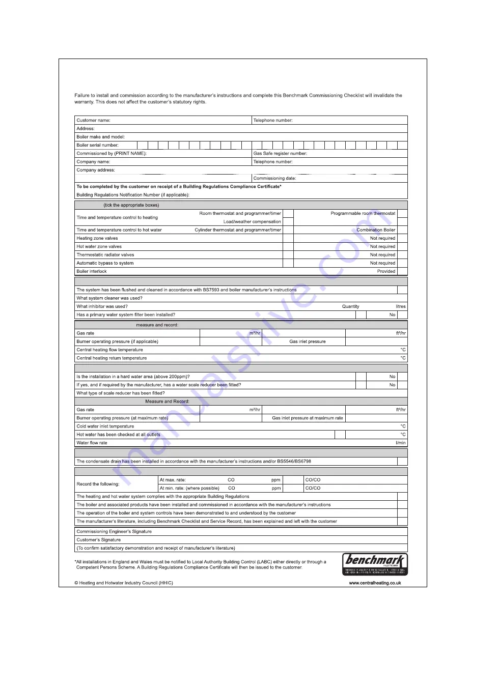
This Commissioning Checklist is to be completed in full by the competent person who commissioned the boiler as a means of demonstrating 
compliance with the appropriate Building Regulations and then handed to the customer to keep for future reference.

GAS BOILER SYSTEM COMMISSIONING CHECKLIST

CONTROLS

Optimum start control

Fitted
Fitted
Fitted
Fitted

ALL SYSTEMS

Yes

Yes

CENTRAL HEATING MODE 

OR

mbar

OR

mbar

COMBINATION BOILERS ONLY

Yes
Yes

DOMESTIC HOT WATER MODE

OR

mbar

OR

mbar

Yes

Temperature

CONDENSING BOILERS ONLY

Yes

ALL INSTALLATIONS

AND

²

Ratio

AND

²

Ratio

Yes
Yes
Yes
Yes

Summary of Contents for 0010027591

Page 1: ...Installation and main tenance instructions Energy 2 30c P GB IE...

Page 2: ...siphon 18 7 9 Filling the domestic hot water circuit 18 7 10 Checking the gas setting 19 7 11 Checking leak tightness 20 8 Adapting the unit to the installation 21 8 1 Setting the burner anti cycling...

Page 3: ...Contents 0020283671_03 Energy 2 Installation and maintenance instructions 3 J Technical data 44 Index 47...

Page 4: ...able documents The use of the product in vehicles such as mobile homes and caravans is not classed as intended use Units that are not classed as vehicles are those that are installed in a fixed and pe...

Page 5: ...paint 1 4 6 Risk of death from electric shock There is a risk of death from electric shock if you touch live components Before commencing work on the product Unplug the mains plug Or disconnect the pr...

Page 6: ...ing salons painter s or joiner s workshops cleaning businesses or similar locations choose a separate installation room in which the room air is technically free of chemical substances 1 4 12 Risk of...

Page 7: ...ralheating co uk 3 Product description 3 1 Compartment Ventilation The boilers are very high efficiency appliances As a consequence the heat loss from the appliance casing during operation is very low...

Page 8: ...he weight that can be lifted by a single person 4 1 1 General Hold the load as close as possible to your body Avoid rotational movements Instead reposition your feet If the unit is being lifted by two...

Page 9: ...n on the top of the air flue pipe 4 5 Minimum clearances C C A B D Minimum clearance A 150 mm top air flue gas connection 20 mm air flue gas connection on the rear B 150 mm C 5 mm 70 mm if the side se...

Page 10: ...fore using the product it must be checked by a qual ified person in order to ensure that it is permanently se curely fastened and is safe to use 4 8 Removing installing the front casing 4 8 1 Removing...

Page 11: ...ution Risk of damage caused by incorrect gas connection installation Excess test pressure or operating pres sure may cause damage to the gas valve assembly Check the leak tightness of the gas valve as...

Page 12: ...the non neutralised condensate If you cannot guarantee that the materials from which the drain pipework is made are suitable install a system for neutralising the condensate Note The condensate drain...

Page 13: ...min 5 6 1 2 External soil and vent pipe 19mm min 30mm 5 6 1 3 External termination into a gulley or hopper 19mm min 30mm 5 6 1 4 Internal termination into combined sink waste 30mm 19mm min 5 6 1 5 Int...

Page 14: ...electronics box B B A Follow the instructions in the specified sequence 5 7 2 Closing the electronics box Follow the instructions in the reverse order 5 7 3 Cable route 1 2 1 24 V eBUS cable route 2...

Page 15: ...tallation type Condition If installing a multi circuit control Change the pump mode d 18 from Eco intermittent pump operation to Comfort continuous pump opera tion Condition If you are connecting a co...

Page 16: ...he display 8 Press and hold the button for 3 seconds to finish the check programmes End is shown in the display The display switches to the basic display Note If you do not press any button for 15 min...

Page 17: ...water is less than 6 5 or more than 8 5 Total heating output Water hardness at specific system volume 1 20 l kW 20 l kW 50 l kW 50 l kW kW ppm CaCO mol m ppm CaCO mol m ppm CaCO mol m 50 300 3 200 2...

Page 18: ...tomatic air vent and the hydraulic console 2 Fill with water until the required filling pressure is reached Recommended filling pressure 1 to 1 5 bar The heating and hot water functions cannot be acti...

Page 19: ...to the test nipple 2 5 Open the gas stopcock 1 6 Start up the product with check programme P 01 in stallation with eBUS control 7 In addition ensure that maximum heat can be dissip ated by fully open...

Page 20: ...on If the system is to be treated with an inhibitor it should be applied at this stage in accordance with the manufacturer s instructions Further information can be obtained from Sentinel Betz Dearbor...

Page 21: ...installation If you have installed a low loss header in the heating install ation you should switch off the speed regulation and set the pump output to a fixed value If required change the setting of...

Page 22: ...intenance in tervals The inspection may require maintenance to be carried out earlier depending on the results Inspection and maintenance work Overview Page 37 10 3 Procuring spare parts The original...

Page 23: ...pane Propane CO at full load 10 3 1 10 1 1 Set for Wobbe index W 21 34 kW h m 21 34 kW h m O at full load 5 1 0 8 vol 5 1 0 8 vol CO at full load 250 ppm 250 ppm CO CO 0 0031 0 0031 If the setting is...

Page 24: ...lace the burner 2 Install the two new burner seals 10 9 Checking the ignition electrode 1 2 3 4 5 1 Disconnect the connection 2 and the earth cable 1 2 Remove the fixing screws 3 3 Carefully remove th...

Page 25: ...15 Checking the pre charge pressure of the expansion vessel 1 Measure the pre charge pressure of the expansion ves sel at the vessel valve Condition Pre charge pressure 0 075 MPa 0 75 bar Top up the e...

Page 26: ...lose the service valves in the heating flow and in the heating return 6 Close the service valve in the cold water pipe 7 Drain the product if you want to replace water bearing components of the produc...

Page 27: ...the pump cable to the electronics box 11 6 5 Replacing the expansion vessel B C 1 2 3 A D 1 Undo the nut 3 2 Remove both screws on the support plate 1 3 Remove the support plate 4 Pull out the expans...

Page 28: ...stall the new volume flow sensor 4 Plug in the plug 11 6 10 Replace the pressure sensor 1 2 1 Pull out the plug 2 Remove the clip 1 3 Remove the pressure sensor 2 4 Install the new pressure sensor 5 R...

Page 29: ...g function is activated The function is active for 15 minutes P 06 Purging the heating circuit The prioritising diverter valve is moved to the heating position The function is activated in the heating...

Page 30: ...uit s shunt pump Current value off on Not adjustable d 13 Status of the hot water circuit s circulation pump Current value off on Not adjustable d 14 Operating mode of the modulating pump 0 5 0 variab...

Page 31: ...omitted 8 eBUS remote control 9 Legionella protection pump 10 Solar valve 1 Adjustable d 28 Function of relay 2 multi functional module 1 10 1 Circulation pump 2 External pump 3 Cylinder charging pump...

Page 32: ...Not adjustable d 69 Number of unsuccessful ignitions at 2nd attempt Current value Not adjustable d 70 Operation of the diverter valve 0 2 0 Normal operating mode DHW and heating mode 1 Mid position p...

Page 33: ...ng mode No requirement S 01 Heating mode Fan prerun S 02 Heating mode Pump prerun S 03 Heating mode Burner ignition S 04 Heating mode Burner on S 05 Heating mode Pump fan overrun S 06 Heating mode Fan...

Page 34: ...F 01 Fault Return temperature sensor NTC plug not plugged in or has come loose multiple plug on the PCB not plugged in correctly interruption in cable harness NTC sensor defective F 10 Short circuit...

Page 35: ...splay and PCB replaced at same time and Device Specific Number not reset wrong or missing output coding resistor F 71 Fault Flow return temperature sensor Flow temperature sensor signalling constant v...

Page 36: ...4 5 10 11 6 13 X51 X35 X20 X40 X51 X30 X2 X21 X41 X22 X14 L N 24V RT BUS Burner off RT 230Vac X1 FUS X106 X32 X90 X12 X35 X1 L N RT 230Vac X35 4 1 3 2 eBUS RT 24V Burner off X106 1 3 4 1 3 3 1 2 M 1...

Page 37: ...ary approx 0 03 MPa 0 3 bar below the system filling pressure X 9 Remove the gas air mixture unit X 10 Check the seals in the combustion area If you see any damage replace the seals Replace both burne...

Page 38: ...ater pipes 75 mm E Below eaves 200 mm F Below balconies or car port roofs 200 mm G From vertical wastewater pipes or down pipes 150 mm H From external or internal corners 200 mm I Above floors roofs o...

Page 39: ...is manual 1 Dimensions D E F and G These clearances may be reduced to 25 mm without affecting the performance of the boiler In order to ensure that the con densate plume does not affect adjacent surfa...

Page 40: ...Energy 2 0020283671_03 H Commissioning Checklist Heating and Hotwater Industry Council HHIC www centralheating co uk Benchmark Commissioning and Servicing Section It is a requirement that the boiler i...

Page 41: ...the appropriate Building Regulations and then handed to the customer to keep for future reference GAS BOILER SYSTEM COMMISSIONING CHECKLIST CONTROLS Optimum start control Fitted Fitted Fitted Fitted...

Page 42: ...system is serviced regularly and that the appropriate Service Interval Record is completed Service Provider SERVICE RECORD SERVICE 01 AND AND SERVICE 02 AND AND SERVICE 03 AND AND SERVICE 04 AND AND S...

Page 43: ...to set boiler to minimum rate contact Technical Helpline for advice CHECK CO AND COMBUSTION RATIO AT MINIMUM RATE With boiler still set at minimum rate insert analyser probe into flue gas sampling po...

Page 44: ...lume pH value between 3 5 and 4 0 at 50 30 C 2 55 l h P heating at nominal flow T 20 K 0 025 MPa 0 250 bar Technical data Power loading G31 Energy 2 30c A P GB Maximum heat output 25 kW Effective outp...

Page 45: ...m h CE number PIN CE 0063CP3646 Flue gas mass flow rate in heating mode at P min 4 49 g s Flue gas mass flow rate in heating mode at P max 14 5 g s Flue gas mass flow rate in do mestic hot water mode...

Page 46: ...tructions Energy 2 0020283671_03 Technical data Electrics Energy 2 30c A P GB Electrical connection 230 V 50 Hz Built in fuse slow blow T2 2A 250V Max electrical power consump tion 78 W Standby electr...

Page 47: ...High efficiency pump output 21 I If you smell flue gas 5 If you smell gas 4 Inspection work 22 37 Installation site 5 Intended use 4 L Leak tightness 20 25 28 Liquid gas 5 11 M Maintenance work 22 37...

Page 48: ...9 Technical helpline 0330 100 7679 After sales service 0330 100 3142 www glow worm co uk 0020283671_03 28 07 2019 These instructions or parts thereof are protected by copyright and may be reproduced o...

Reviews: