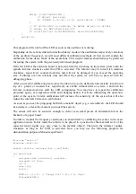
Global Specialties ARX-MSP Manual Download Page 12

    while(1)

    {

freq=0;

for (i=0; i<100; i++) {
    count72kHz=0; // This counter is incremented in timer interrupt

    FrontLED(OFF);
    while (count72kHz<72) {

// Detect level change
newlevel = PIND & (1<<2);

if (oldlevel != newlevel) {
    oldlevel = newlevel;

    freq++;
    FrontLED(ON);

}

    }

}  
sprintf(s,"%5d\n\r",freq);

SerWrite(s,7);

    }

    return 0;
}

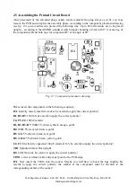
2.7 The debugging procedure

If   the   system   does   not   work   as   expected,   we   will   have   to   start   the   debugging   procedure. 
Unfortunately we cannot provide as many debugging options as for the basic ASURO-system. The 
use of a multimeter may help to debug the system.

Please start by checking the correct compilation of the test program. Has the program really
been flashed? Proceed by checking the soldering locations and the polarities and values for
the components.

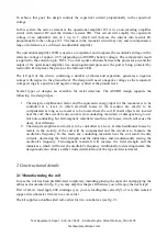
Check the connections of the coil system for correct removing of the isolations and applying
the solder. Did you really remove the isolation? At a 

deactivated

 (!) robot you should be able

to monitor a resistance of 30Ω at the terminals for the coil.
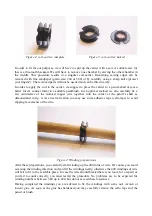
At much higher measured resistor values, the cable has not been connected correctly, some
isolation at the copper cable has not been removed properly – preventing good conductivity
- or the thin copper wire of the coil has been disrupted at the assembly phase. The last
problem often occurs in the neighbourhood of the capacitor.
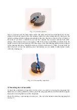
At much lower measured resistor values, you may locate a short circuit at the printed circuit 
board or in the coil. You are now advised to remove the cable from the screw terminal and to 
repeat the measurement of the resistance value at the screw terminal. If the resistance is 
much higher than 30 Ohms, you may locate the short circuit area at the coil module. 

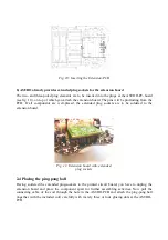
At an activated robot you should be able to monitor an operating voltage in the range 4.5 ..
5.5V between the terminals GNDOUT1 and VCCOUT1. If the operating voltage does not
meet   these   specifications   the   battery  may  be   empty,   the   robot   may  be   deactivated,   the
connections for the battery compartment may be interrupted or a cold soldering point occurs
in the neighbourhood of the rear extended plugs at the extension board or the robot itself.

The voltage for the operational amplifier may be monitored between pin 4 (minus) (at the
bottom left side if the mark at the IC is at the topside) and pin 8 (plus) (at the top right side).
The voltage should be at least 2V higher than the battery voltage.

Test Equipment Depot - 800.517.8431 - 99 Washington Street Melrose, MA 02176

 TestEquipmentDepot.com 

Summary of Contents for ARX-MSP

Page 1: ...ARX MSP Minesweeper Kit 99 Washington Street Melrose MA 02176 800 517 8431 TestEquipmentDepot com...

Page 2: ...y open pot core allows the magnetic field to expand into the surrounding free field and to be influenced by neighbouring metallic objects Fig 1 displays the schematic diagram The resonant circuit cons...

Page 3: ...e equivalent energy input for the resonator is to be controlled at a level in which electrical losses in the resonator are exactly to be compensated as long as no metal is to be located near the coil...

Page 4: ...centimetres of the isolated copper wire together with the carrier at the pencil s shaft as demonstrated in fig 4 As an extra fixation you may use some adhesive tape cello tape to avoid slipping moveme...

Page 5: ...y the heated top for some time until the isolation has been removed and a thin layer of soldering tin is covering the wire Warning the generated smoke may cause damage to your health and should not be...

Page 6: ...f the isolation layer at the thin copper wires the soldering quality and any ruptures of the soldering and cables Should the resistance value be much lower 10 you must check for short circuits at or n...

Page 7: ...cing the photo transistors T9 and T10 as well as the LED D11 from the PC board These activities require a removal of the ping pong ball The easiest way to proceed is to heat the components which are t...

Page 8: ...ed the extended plug sockets are to be soldered to the extension board 2 4 Placing the ping pong ball Having soldered the extended plug sockets to the printed circuit board you have to unplug the exte...

Page 9: ...et be careful to apply the correct polarity D1 D2 D3 1N4148 be careful to apply the correct polarity C4 C5 C6 100nF ceramic R1 R2 R3 R7 10k 5 brown black orange gold R4 220 5 red red brown gold R5 1k...

Page 10: ...ocedure Having attached the ping pong ball including the coil and having completed the PCB assembly you can now insert the PCB into the deactivated robot Please check the isolation of the components c...

Page 11: ...tion on top of a plastic or wooden box respectively on a table without nails or screws and turn the trimmer counter clockwise until the LED extinguishes You may have to repeat the calibration procedur...

Page 12: ...eventing good conductivity or the thin copper wire of the coil has been disrupted at the assembly phase The last problem often occurs in the neighbourhood of the capacitor At much lower measured resis...

Reviews: