Global Hobby AK-18 Instructions Manual Download Page 14

14

q

5) Install the motor mount assembly to the fire-

wall using the four 4mm x 20mm machine screws
and four 4mm flat washers.  Tighten the screws com-
pletely to secure the engine mount assembly in place.
See photo # 18 below.

Photo # 18

q

6) Mark and drill a hole through the firewall for

the throttle pushrod housing using a 7/64” drill bit.
Position the hole level with the throttle arm and just
to the outside edge of the motor mounting beam.

q

7) Using a ruler and a pen, measure and place a

mark on the forward bulkhead 1-1/8” down from the
top of the wing saddle and 5/8” out from the inside
edge of the fuselage side.  See figure # 11 below.

INSTALLING THE THROTTLE PUSHROD

Figure # 11

q

8)

Using a 7/64 drill bit, carefully drill a hole

through the forward bulkhead at the mark made.

q

9) Slide the 3mm x 250mm pushrod housing

through the hole in the firewall, through the hole in
the forward bulkhead, and into the servo compart-
ment.  Leave about 1/4” of the housing extending
beyond the front of the firewall.

q

10) Apply a couple of drops of Kwik Bond Thin

C/A to the pushrod housing where it exits the fire-
wall and where it passes through the forward bulk-
head.  This will secure the housing in place.

q

11) Using a modeling knife, cut off the nylon

pushrod housing 1/8” past the back edge of the for-
ward bulkhead.

q

12) Notice one end of the 1.5mm x 250mm push-

rod wire has a Z-Bend premade in it and the other
end is plain.  Slide the plain end of the wire into the
end of the pushrod housing at the firewall.  Remove
the throttle arm from the engine and attach the Z-Bend
to the hole farthest out in the throttle arm.  Reattach
the throttle arm to the engine.

q

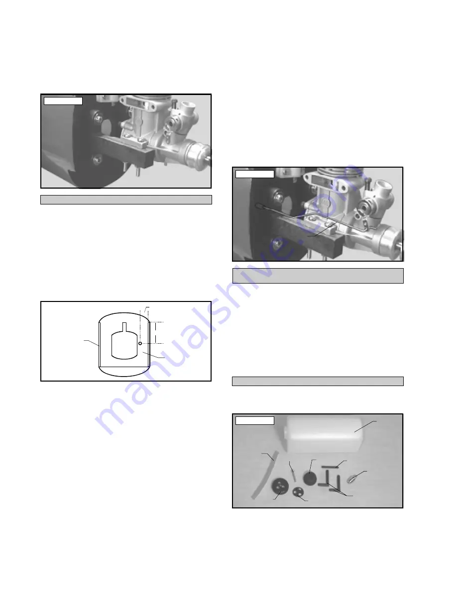
13) Using a pair of pliers, carefully bend the

throttle pushrod wire until the wire is aligned with
the throttle arm and does not bind when the throttle
barrel is rotated.  See photo # 19 below.

Photo # 19

PARTS REQUIRED

q

{1} 280cc Molded Fuel Tank

q

{1} 4mm x 28mm Nylon Pick-Up Tube

q

{2} 4mm x 28mm Prebent Nylon Vent Tube

q

{1} 3mm x 18mm Self Tapping Screw

q

{1} Length of Fuel Tubing

q

{1} Metal Weighted Pick-Up

q

{1) Nylon Fuel Cap

q

{1} Rubber Stopper

q

{1} Nylon Backplate

STOPPER ASSEMBLY

FUEL TANK

q

1) Identify each of the parts that make up the

fuel tank assembly.  See photo # 20 below.

Photo # 20

q

2) Using a modeling knife, cut the silicon fuel

tubing to 3-3/4” long.  Connect one end of the tubing
to the weighted fuel pick-up.

1-1/8”

5/8”

Fuselage

Side

Forward

Bulkhead

Pushrod

Wire

Tank

Clunk

Silicon

Tube

Rubber

Stopper

Backplate

Screw

Pickup

Tube

Vent

Tubes

Cap

Summary of Contents for AK-18

Page 1: ...ull size Yak 18 might have been like with your new Global Yak 18 ARF The Global Yak 18 is built by master craftsmen utilizing the finest grades of balsa light ply foam and fiberglass It s covered using heat shrink polyester covering material just like you would use if you were building it yourself A complete set of high quality hardware is in the box This includes the fuel tank wheels pushrods cle...

Page 2: ...rol Horn 17 Installing the Rudder Pushrod 18 Aileron Pushrods 19 Installing the Control Horns 19 Installing the Aileron Pushrods 19 Cowl 19 Installing the Cowl Blocks 19 Mounting the Cowl 20 Installing the Fuel Filler 20 Installing the Fuel Lines 20 Canopy 21 Canopy Preparation 21 Mounting the Canopy 21 Final Assembly 21 Installing the Receiver and Battery 21 Installing the Switch 22 Balancing 22 ...

Page 3: ... Split Washers q 4 4mm Hex Nuts q 1 Plywood Dihedral Brace q 1 Precovered Wing Bolt Doubler q 2 Precovered Aileron Servo Hatches q 4 10mm x 10mm x 20mm Hardwood Blocks q 4 3mm x 12mm Wood Screws q 4 3mm Flat Washers q 2 4mm x 45mm Socket Cap Screws q 2 4mm Flat Washers q 1 10 x 6 Propeller for 40 Size Engines q 1 280cc Molded Fuel Tank q 1 4mm x 28mm Nylon Pick Up Tube q 2 4mm x 28mm Prebent Nylon...

Page 4: ... q Paper Towels q Rubbing Alcohol q Wire Cutters q 4mm Hex Driver q Magnum 12V Electric Starter 361006 q Magnum 12V Fuel Pump 237377 q Magnum Locking Glow Clip 237440 q Global 12V Battery 110171 q Global 12V Charger 110270 q Magnum Power Panel 237390 q Global Field Buddy Flight Box 233072 q Magnum 4 Way Wrench 237420 q 1 Ernst Charge Jack 124 q 1 Cirrus On Board Battery Indicator 444762 q 2 Willia...

Page 5: ...e needed for assembly Cover your workbench with an old towel or brown paper both to protect the aircraft and to protect the table Keep a couple of jars or bowls handy to hold the small parts after you open the bags NOTE Please trial fit all the parts Make sure you have the correct parts and that they fit and are aligned properly before gluing This will assure proper assembly Since the YAK 18 is ha...

Page 6: ...to 1 q 12 Using a pencil carefully outline the loca tions of the two wood blocks and the servo onto the bottom of the servo hatch q 13 Remove the parts from the hatch Using Kwik Bond 5 Minute Epoxy glue the two wood blocks into place on the servo hatch Allow the epoxy to fully cure before proceeding It is very important that you use epoxy in this situation C A glues will not adhere as well to the ...

Page 7: ...ing using a heat gun to se cure the plugs in place See figure 4 below INSTALLING THE DIHEDRAL BRACE q 24 Look at the surface of each root rib on both wing halves Notice how the excess covering mate rial overlaps onto them Using a modeling knife care fully cut away the covering from both of the root ribs leaving about 1 16 of covering overlapping so it does not pull away It is important that the co...

Page 8: ... When the epoxy has fully cured double check the center section joint If any gaps are present mix a small amount of Kwik Bond 30 Minute Epoxy to carefully fill any remaining gaps Allow the epoxy to fully cure Photo 6 PARTS REQUIRED MAIN GEAR INSTALLATION INSTALLING THE MAIN GEAR WIRES q 2 Prebent Main Gear Wires q 2 55mm Diameter Wheels q 4 Landing Gear Straps q 8 3mm x 12mm Wood Screws q 2 Wheel ...

Page 9: ...ral angle much easier INSTALLING THE WING BOLT DOUBLER q 7 While holding the doubler in place use a pen and draw around the doubler to outline it onto the wing s surface q 8 Remove the wing bolt doubler Using a mod eling knife carefully remove the covering from just inside the outline on the wing q 9 Mix up a small quantity of Kwik Bond 5 Minute Epoxy and use it to glue the wing bolt dou bler to t...

Page 10: ...use the stabilizer has to slide in place through the fuselage we suggest you apply a liberal amount of epoxy to only the gluing surface of the stabilizer This will prevent spreading epoxy over the entire length of one half of the stabilizer when you slide it in place After the epoxy has cured use more epoxy to fill in any gaps that may exist that were not filled previously MOUNTING THE HORIZONTAL ...

Page 11: ...up a generous amount of Kwik Bond 30 Minute Epoxy Apply a thin layer to the mount ing slot in the top of the fuselage and to the sides and bottom of the vertical stabilizer mounting area Apply epoxy to the bottom edge of the dorsal fin and to the top of the fuselage also Set the stabilizer in place and realign Double check all of your mea surements once more before the epoxy cures Hold the stabili...

Page 12: ...lkhead 7 8 down from the top of the wing saddle and 3 8 out from the inside edge of the fuselage side See figure 9 at top right Figure 9 q 10 Using a 7 64 drill bit carefully drill a hole through the forward bulkhead at the mark made q 11 Using a ruler and pen measure and place a mark on the forward servo tray support bulkhead 3 8 down from the top of the wing saddle and 1 4 out from the inside ed...

Page 13: ...n the beams using a pencil For the engine to align properly with the front of the cowling it is important that the front edge of the engine s drive washer be 4 5 8 in front of the back surface of the mounting beams q 3 When satisfied with the alignment of the en gine remove the beams from the clamp and drill 3 32 pilot holes through the mounting beams at the four engine mounting hole locations Dou...

Page 14: ...head This will secure the housing in place q 11 Using a modeling knife cut off the nylon pushrod housing 1 8 past the back edge of the for ward bulkhead q 12 Notice one end of the 1 5mm x 250mm push rod wire has a Z Bend premade in it and the other end is plain Slide the plain end of the wire into the end of the pushrod housing at the firewall Remove the throttle arm from the engine and attach the...

Page 15: ... towards the top of the tank See photo 22 below Photo 22 q 9 With the stopper assembly in place the weighted pick up should be about 3 8 from the rear of the tank and move freely within the tank Adjust the length of the tube accordingly q 10 When satisfied with the alignment of the stopper assembly tighten the 3mm x 18mm self tap ping screw until the stopper expands and seals the tank opening Do n...

Page 16: ...plit Elevator Pushrod Assembly q 2 Nylon Clevises q 1 Adjustable Servo Connector Assembly q 2 Nylon Control Horns w Backplates q 4 2mm x 25mm Machine Screws INSTALLING THE CONTROL HORNS q 1 Position one elevator control horn on the bot tom of each elevator half The centerline of each horn should be 3 4 out from the fuselage sides at the hinge line Position the control horns so the cle vis attachme...

Page 17: ...hoto 25 q 8 Install one adjustable servo connector through the third hole out from the center of one servo arm You may have to enlarge the hole in the servo arm to accom modate the servo connector Remove the excess mate rial from the arm See figure 15 at top right Figure 15 After installing the adjustable servo connector apply a small drop of Kwik Bond thin C A to the nut This will prevent the nut...

Page 18: ...ter of one dual arm servo arm You may have to enlarge the holes in the servo arm to accommodate the servo connectors Remove the excess material from the arm See figure 17 below Figure 17 After installing the adjustable servo connectors apply a small drop of Kwik Bond thin C A to the nuts This will prevent the nuts from coming loose during flight q 9 Slide the adjustable servo connector servo arm a...

Page 19: ...d into the outermost hole in the servo arm You may have to enlarge the hole so the wire will fit through q 7 With the aileron and servo arm in neutral carefully adjust the nylon clevis by either turning it in or out until the clevis pin lines up with the holes in the control horn q 8 When satisfied with the fit attach the clevis to the fourth hole out from the bottom of the clevis See photo 29 bel...

Page 20: ...es use a needle valve ex tension made out of scrap pushrod material to access the high speed needle valve from outside the cowl and cylinder head clearance Remove the cowl and install the muffler onto the engine Make the cutout in the cowl for muffler clearance and reinstall the cowl to check the fit A Dremel Tool with a rotary sanding bit works best to make these cutouts q 11 Remove the cowl Usin...

Page 21: ...hat only the canopy frame is exposed Paint the canopy using Topflite Lusterkote Olive Drab spray paint following the manufacturer s recommendations Allow the paint to dry then re move the masking tape FINAL ASSEMBLY INSTALLING THE RECEIVER AND BATTERY q 1 Plug the servo leads and the switch lead into the receiver Plug the battery pack lead into the switch also You may want to use an extension lead...

Page 22: ...the battery and receiver forward or if this is not possible stick weight onto the firewall or use a brass heavy hub spinner hub similar to those offered by Harry Higley When balanced correctly the airplane should sit level or slightly nose down when you lift it up with your fingers BALANCING Once you have flown and trimmed the Yak 18 the balance point can be moved forward or aft up to 3 8 to chang...

Page 23: ...hey do not release in the air Cut a piece of fuel line into five 1 4 pieces Unsnap the clevises and slip one piece over each clevis Snap the clevises back in place and slide the tubing up over them q 1 Completely charge your transmitter and re ceiver batteries before your first day of flying q 2 Check every bolt and every glue joint in the Yak 18 to ensure that everything is tight and well bonded ...

Page 24: ..._________________________________________ ______________________________________________ ____________________________________________ ___________________________________________ _ _ _ _ _ _ _ _ _ _ _ _ _ _ _ _ _ _ _ _ _ _ _ _ _ _ _ _ _ _ _ _ _ _ _ _ _ _ _ _ _ _ _ _ _ _ _ _ _ _ _ _ _ _ _ _ _ _ _ _ _ _ _ _ _ _ _ _ _ _ _ _ _ _ _ _ _ _ _ _ _ _ _ _ _ _ ___________________________________________ ______...

Page 25: ...ight C Nose drops If C Remove nose weight Yaw Into wind do inside A Wings level throughout If A Trim is correct loops using only elevator B Yaws to right in both If B Add left rudder trim Repeat tests doing inside and outside loops outside loops from C Yaws to left in both If C Add right rudder trim inverted entry inside and outside loops D Yaws to right on inside If D Add left aileron trim and le...

Page 26: ...26 ...

Page 27: ...ed q Wrong Size q Missing q Wrong Shape If you checked any of the boxes above did you contact our Customer Service Department to re solve the problem q Yes q No 7 Was any of the assembly difficult for you If yes please explain q Yes q No _____________________________________ _____________________________________ _____________________________________ _____________________________________ 8 What did...

Page 28: ...Fold along dotted line Fold along dotted line Global Hobby Distributors Attn Customer Service Department 18480 Bandilier Circle Fountain Valley CA 92728 Post Office will not deliver without proper postage ...

Reviews: