background image

STATUS

QUEUE REVIEW

ZONES

FAULTS

KEYPAD

CONTROLS

DISABLEMENTS

FIRE

FAULT

PRE-ALARM

TEST

DISABLED

SYSTEM ON

ALARM FAULT

SUPPLY FAULT

SYSTEM FAULT

ENTER

ESC

DELAYS

ACTIVE

SELECTED

DETECTORS

SOUNDERS

DISABLE

AUXILIARY

RELAYS

SOUNDERS

ACTIVATE/ SILENCE

SYSTEM RESET

LAMP TEST

BUZZER

SILENCE

DISABLED

TEST

FAULT

FIRE

1

2

3

4

5

6

7

8

MANUFACTURED IN THE E.U. TO THE

REQUIREMENTS OF EN54 Pt 2 & Pt 4 1999

OPERATION

1.5 READ THE FIRE, FAULT, TEST AND DISABLED QUEUES
(Access level 1 - General User)

Fire, fault, test, and disabled messages are shown on the LCD display.

The LCD has a limited display area. If more messages exist than can be shown on the LCD display the
FIRE, FAULT, TEST or DISABLED LEDs illuminate on the QUEUE REVIEW area of the fascia. The following
procedure describes how to display the additional messages.

If the QUEUE REVIEW - FIRE

is flashing RED....

Press the QUEUE REVIEW - FIRE

to display the first queued message.

Press the button again to review the next queued message. Do this until all
messages have been reviewed. The LED stops flashing RED, but remains lit,
once all messages have been displayed.

After 20 seconds the first fire event will be re-displayed.

LED

button

If the QUEUE REVIEW - FAULT

is flashing AMBER....

Press the QUEUE REVIEW - FAULT

The LED illuminates steady AMBER when all

messages have been displayed.

After 20 seconds the first fault will be re-displayed unless a fire has occurred in
which case the first fire will be re-displayed instead.

LED

button to display the first queued message.

Press the button again to review the next queued message. Do this until all
messages have been reviewed.

If the QUEUE REVIEW - TEST

is illuminated AMBER....

Press the QUEUE REVIEW - TEST

to display the Zones in test mode.

Sometimes not all the Zones in test mode can be displayed at once, in this case
press the button again to see the next set of Zones in test mode.

After 15 seconds the display will return to it’s quiescent state (usually the
company name and current time).

LED

button

If the QUEUE REVIEW -DISABLED

is illuminated AMBER....

Press the QUEUE REVIEW -DISABLED

to display the disablements on

the LCD.

LED

button

Sometimes not all the disablements can be displayed at once, in this

case press the button again to see the next set of disablements.

After 15 seconds the display will return to it’s quiescent state (usually the
company name and current time).

TEST

DISABLED

G L O B A L

F I R E

E Q U I P M E N T

JUNiOr

FIRE

FAULT

6

JUNIOR V3 - OPERATION & MAINTENANCE MANUAL - REVISION 2.3 - 17-SEP-2005

www.acornfiresecurity.com

www.acornfiresecurity.com

Summary of Contents for JUNIOR V3

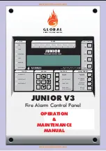
Page 1: ... ACTIVE SELECTED DETECTORS SOUNDERS DISABLE AUXILIARY RELAYS SOUNDERS ACTIVATE SILENCE SYSTEM RESET LAMP TEST BUZZER SILENCE DISABLED TEST FAULT FIRE 1 2 3 4 5 6 7 8 MANUFACTURED IN THE E U TO THE REQUIREMENTS OF EN54 Pt 2 Pt 4 1999 F I R E E Q U I P M E N T JUNIOR V3 Fire Alarm Control Panel OPERATION MAINTENANCE MANUAL www acornfiresecurity com www acornfiresecurity com ...

Page 2: ...y Relays 1 10 4 Enable Disable Zones 1 11 If the panel displays a fault 1 12 If the panel displays a pre alarm SECTION 2 MAINTENANCE 2 4 5 5 6 7 8 9 10 12 12 13 13 14 14 14 15 16 16 16 18 19 20 G LO B A L F I R E E Q U I P M E N T 1 Some functions are only available at Authorized User level of Access To enter this mode a valid user Code has to be entered using the panel s front display keypad The ...

Page 3: ...his could be an open or short circuit If the LED is AMBER it indicates that there is a Primary Supply Electrical mains Fault a Battery Fault or that there is an Earth Fault If the LED is AMBER it indicates that there is 5 Volt fault or a processor program failure Fire Zone indicator LEDs SUPPLY FAULT SYSTEM FAULT ZONES 1 2 3 4 5 6 7 8 9 10 OPERATION SECTION 1 2 STATUS QUEUE REVIEW ZONES FAULTS KEY...

Page 4: ... Note that this button will only operate if at least one detector has been set for SELECTIVE DISABLEMENT If the LED is AMBER it means that the selected detectors are isolated Pressing this button will enable disable all sounders in the system This LED will be lit when sounders are disabled Pressing this switch disables or enables all the relay and I O module outputs If the LED is lit it means that...

Page 5: ...er pressing The STATUS FIRE will remain lit RED button LED LED At the fire control panel the STATUS F I R E w i l l illuminate RED The fire control panel buzzer will sound continuously The location of the alarm or alarms will be shown on the fire control panel L E D LCD display 1 2 ALARM Authorised User Access If the fire alarm control panel signals an ALARM the following events will take place Th...

Page 6: ...D extinguishes SOUNDERS SOUNDERS SOUNDERS ACTIVATE SILENCE ACTIVATE SILENCE ACTIVATE SILENCE button 1 4 SOUND AND SILENCE THE ALARMS EVACUATION Authorised User Access This section shows you how to turn on and turn off all the sounders in an installation It is identical to a fire drill procedure This procedure should be used if There has been an alarm and the alarm condition no longer exists There ...

Page 7: ... display area If more messages exist than can be shown on the LCD display the FIRE FAULT TEST or DISABLED LEDs illuminate on the QUEUE REVIEW area of the fascia The following procedure describes how to display the additional messages If the QUEUE REVIEW FIRE is flashing RED Press the QUEUE REVIEW FIRE to display the first queued message Press the button again to review the next queued message Do t...

Page 8: ...all other times the sounders and I O modules will operate immediately a fire is detected o enable or disable these delays press the S button Note that it is also possible via the programming functions to set to automatically turn off at night DELAYS After entering User Access code t DELAYS ACTIVE DELAYS ACTIVE For details on the programmable features and delays refer to the Installation Commission...

Page 9: ...s properly and that the LCD display is fully functional G LO B A L F I R E E Q U I P M E N T JUNiOr 8 JUNIOR V3 OPERATION MAINTENANCE MANUAL REVISION 2 3 17 SEP 2005 STATUS QUEUE REVIEW ZONES FAULTS KEYPAD CONTROLS DISABLEMENTS FIRE FAULT PRE ALARM TEST DISABLED SYSTEM ON ALARM FAULT SUPPLY FAULT SYSTEM FAULT ENTER ESC DELAYS ACTIVE SELECTED DETECTORS SOUNDERS DISABLE AUXILIARY RELAYS SOUNDERS ACT...

Page 10: ...N 1 8 PERFORM A FIRE DRILL Access Level 2 or Authorised User Access To end the fire drill press the The following will occur The sounders stop sounding The extinguishes button LED SOUNDERS ACTIVATE SILENCE SOUNDERS ACTIVATE SILENCE EVACUATE IN ACCORDANCE WITH THE SITE PROCEDURE G LO B A L F I R E E Q U I P M E N T JUNiOr 9 JUNIOR V3 OPERATION MAINTENANCE MANUAL REVISION 2 3 17 SEP 2005 To start th...

Page 11: ... indication The message DETECTOR TEST MODE will be displayed on the LCD The Zones in test mode will be displayed on the LCD ALL ZONES SYSTEM RESET Indication of Caretaker Test Mode ALARM SILENCE will not stop this STATUS QUEUE REVIEW ZONES FAULTS KEYPAD CONTROLS DISABLEMENTS FIRE FAULT PRE ALARM TEST DISABLED SYSTEM ON ALARM FAULT SUPPLY FAULT SYSTEM FAULT ENTER ESC DELAYS ACTIVE SELECTED DETECTOR...

Page 12: ...ements Sensor sensitivity Other Detectors and callpoints can only be tested one at a time The LED must be extinguished on the current device before moving on to test the next device Don t use too much smoke spray All disablements for sounders loop and detectors are ignored during Caretaker Test Mode However the LED on disabled detectors will not be lit when the detector is tested all other aspects...

Page 13: ...RS SELECTED DETECTORS When activated The SELECTED DETECTORS will be illuminated The STATUS DISABLED will be illuminated The QUEUE REVIEW DISABLED will be illuminated The disabled detectors can be reviewed using the DISABLED QUEUE REVIEW The SELECTED DETECTORS button will only operate if there is at least one detector set to SELECTIVE DISABLEMENT Re pressing the SELECTED DETECTORS button again will...

Page 14: ... 3 4 5 6 7 8 MANUFACTURED IN THE E U TO THE REQUIREMENTS OF EN54 Pt 2 Pt 4 1999 To disable the relay and I O module outputs press the AUXILIARY RELAYS The AUXILIARY RELAYS illuminates AMBER The STATUS DISABLED illuminates AMBER Re press the AUXILIARY RELAYS button to re enable the relays and I O modules button LED LED The QUEUE REVIEW DISABLED illuminates AMBER LED AUXILIARY RELAYS 1 10 3 AUXILIAR...

Page 15: ...Disable a zone follow the procedure described below 1 Enter either a valid User or Programming Code 2 Select Function 3 1 Zones Disable Assign using the arrow keys Press ENTER when menu 3 is reached 3 Using the arrow keys once more select function 3 1 and press 4 Select the zone to be disabled using the arrow keys and press 5 The present status of the zone is shown To change it press and change th...

Page 16: ...rrows With the retaining clips held in the released position push the SIM CARD forward and down until it is almost horizontal with the main panel board Lift the SIM CARD off the connector To install the replacement SIM CARD locate it on the connector almost horizontally with the main panel board push it up and back gently until the retaining clips snap into position Download the panel configuratio...

Page 17: ...programming functions can be used to check that the panel is operating correctly Note that to use these functions the installer needs to have granted User Access to the following functions By default access is denied 1 Review Historic Log All the functions associated with reviewing events and settings The panel logs all events in an internal event log It can store a rolling 2000 entries When it is...

Page 18: ...sounder operation The settings selected by this function are used by 7 4 Test Zones and 6 4 1 Activate ASET Mode SAM ALL SOUNDERS ON DETECTOR TEST activates the Panel Conventional and Loop Sounders using this function AFTER 7 4 Test Zones and 6 4 1 Activate ASET Mode SAM will NOT change the settings for the zones already in test mode and the loops already in ASET mode Select the Zones you wish to ...

Page 19: ...ing the INITIALIZING message Press ENTER on the Keypad You must now input your Installer access code See page 6 Access Levels You have unlimited attempts but if code entry is not started within 10 seconds then the panel will revert back to it s default screen While entering the code you are allowed up to 5 seconds between key presses The programming functions are arranged using a menu system To se...

Page 20: ... can be photocopied to produce a logbook that conforms to EN54 14 The sample below is for the reference data e g the name of the responsible person whilst the sample on the next page is for entry of event data REFERENCE DATA Name and address Responsible person Date _________________________ ________________________ Date _________________________ ________________________ Date ______________________...

Page 21: ...A SHEET DATE TIME EVENT INITIALS ACTION REQUIRED DATE COMPLETED G LO B A L F I R E E Q U I P M E N T JUNiOr 20 JUNIOR V3 OPERATION MAINTENANCE MANUAL REVISION 2 3 17 SEP 2005 www acornfiresecurity com www acornfiresecurity com ...

Reviews: