


STEP 10: PSU CABLE AND INTERFACE
CABLE CONNECTIONS
To connect the power and ribbon cables please follow the
instructions below.
Step 1:
Connect the PSU cables from the PSUs to the backplane,
full-size CPU card, HDD, FDD, cooling fans and optical
drives power connector.
Figure 28: Bottom Clips of the Drive Bracket
Figure 29: Bracket at the Base of the Chassis
Step 2:
Secure the drive bracket into the chassis by reinserting
the four previously removed retention screws.
Step 0:
STEP 9: CABLING
The 1404150 has the following components accessible at the
front:
Step 2:
The drive interface connectors must be connected to the
CPU card.
Step 0:
STEP 11: FRONT HANDLE INSTALLATION
Two handles are shipped with the 1404150 chassis. The handles are
installed on the sides, at the front of the chassis. Each handle is
secured to the chassis by four retention screws. To install the handles,
please follow the steps below.
Step 1:
Align the retention screw holes on the side of the chassis
with the retention screw holes in the handle.
Step 2:
Insert four retention screws for each handle.
Step 0:
o
1 x Power LED
o
1 x HDD LED
o
1 x Power switch
o
1 x Reset button
These components are all connected to the CPU card with
cables. To correctly connect these cables, please refer to
the technical documentation that came with your CPU card.
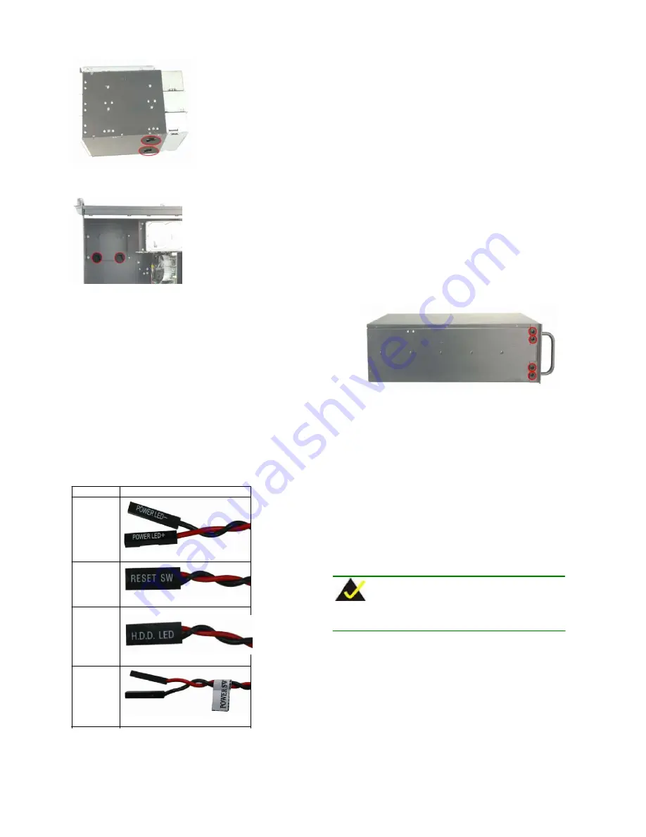
The connectors are listed below:
No.
Name
1
Power LED cable
1
Figure 30: Front Handle Retention Screws
STEP 12: HOLD-DOWN CLAMP AND TOP
COVER REINSTALLATION
On the completion of the above procedures, the hold-down clamp and
cover can be reinstalled. To do this, align the screw holes on both ends
of the hold-down clamp with the screw holes on both sides of the
chassis and reinsert the four previously removed retention screws.
After that, slide the cover back over the chassis and reinsert the six
previously removed retention screws.
CHASSIS MAINTENANCE
„
Fan Replacement
Reset Switch cable
1
HDD LED cable
1
Power switch cable
NOTE:
Please ensure that the power of the computer is switched off
before fan replacement procedure.
There are two 8 cm cooling fans inside the 1404150 chassis. To
replace a fan, please follow the steps below.
Step 1:
Open the front panel. (Please refer to STEP 2: TOP COVER
AND HOLD-DOWN CLAMP REMOVAL)
Step 2:
Remove the fan bracket securing the fan you want to
replace by loosening the two thumbscrews on the upper
right and lower left of the fan bracket.
Table 4: Chassis Connectors
1404150 QIG
Page 1 0


