background image

Page 14

DESIGN

SY

STEM DET

AILS

Expansion Vessel Requirements

Safety valve setting 
(bar)

3.0

Vessel charge 
pressure (bar)

0.5

1.0

1.5

Initial system 
pressure (bar)

0.5

1.0

1.5

2.0

1.0

1.5

2.0

1.5

2.0

Total System 

Volume (l)

Expansion Vessel Volume (l)

25

2.1

3.5

6.5

13.7

2.7

4.7

10.3

3.9

8.3

50

4.2

7.0

12.9

27.5

5.4

9.5

20.6

7.8

16.5

75

6.3

10.5

19.4

41.3

8.2

14.2

30.9 11.7 24.8

100

8.4

14.0

25.9

55.1

10.9

19.0

41.2 15.6 33.1

125

10.4

17.5

32.4

68.9

13.6

23.7

51.5 19.5 41.3

150

12.5

21.0

38.8

82.6

16.3

28.5

61.8 23.4 49.6

Heating System

Open Vented Heating Systems

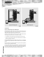
The layout of a typical open vented ‘Y Plan’ heating system is shown in fi gure 8. The 
BoilerMate BP is equally suitable for ‘S’ and ‘W’ plan heating system layouts.

The fl ow pipe from the boiler should rise continuously up to the vent pipe to facilitate 
venting. The heating circuit is taken directly from the boiler and is piped in the 
conventional manner.

The F & E cistern supplied with the thermal store can be fi tted remotely up to 6m above 
the base of the BoilerMate BP. If this cistern is used for the central heating as shown 
in fi gure 8, then the water level in the F&E cistern should be at least 250mm above 
the highest point on the system including the radiators and must be high enough to 
provide the minimum head required by the boiler being used.

Sealed Heating Systems

The layout of a typical sealed ‘Y Plan’ heating system is shown in fi gure 9. The BoilerMate 
BP is equally suitable for ‘S’ and ‘W’ plan heating system layouts. A boiler used in a 
sealed heating system must be suitable for this application i.e. must be fi tted with an 
overheat cut-out thermostat. 

It is recommended that the F&E cistern (for the store) is fi tted at a high level in the 
same cupboard as the BoilerMate BP. However it can be fi tted remotely up to 6m 
above the base of the BoilerMate BP. 

The F&E cistern overfl ow/warning pipe should be installed in a material suitable for a 
heating system feed and expansion cistern in accordance with BS5449. 

There shall be no permanent connection to the mains water supply for fi lling the 
system even through a non-return valve without the approval of the Local Water 
Authority. An approved fi lling loop is required with for fi lling the system, which should 
be disconnected after commissioning the system. This should be located adjacent 
to the boiler along with a suitable expansion vessel, pressure gauge, pressure relief 
valve.

The table below can be used for sizing the heating system expansion vessel. The water 
content of the primary heat exchanger is listed in table 1 and a fi gure of 4.5 l/kW of 
installed radiator capacity can be used for a preliminary assessment of the water 
content of the heating system.

The expansion vessel requirements shown in 
table below are based on a maximum boiler 
fl ow temperature of 93°C. The expansion vessel 
must be suitable to accommodate the change 
in volume of the water in the system when 
heated from 10°C to 110°C a sspecifi ed in BS 
5449:1990clause 16.2.

The minimum system pressure should not be 
less than the static head plus 0.5bar i.e. the 
height of the highest point in the system above 
the expansion vessel plus a margin of 0.5 bar.  

Summary of Contents for BMBP125

Page 1: ...oilerMate BMBP 145 BoilerMate BMBP 185 BoilerMate BMBP 215 BoilerMate BMBP 225 All models comply with the Hot Water Association specification for thermal stores For a sealed or an open vented central heating and mains pressure hot water supply system incorporating a thermal store ...

Page 2: ...eme as an option to notifying the Local Authority directly Similar arrangements will follow for Scotland and will apply in Northern Ireland from 1st January 06 CORGI operates a Self Certification Scheme for gas heating appliances These arrangements represent a change from the situation whereby compliance with theBuildingRegulationswasacceptediftheBenchmarkLogbookwascompletedand this was then left ...

Page 3: ...ners or Consultants concerned with the design and installation Please Note We do not therefore accept any responsibility for matters of design selection or specification or for the effectiveness of an installation containing one of our products unless we have been specifically requested to do so All goods are sold subject to our Conditions of Sale and Warranty Terms which are set out at the rear o...

Page 4: ...mary heat exchanger flow C4 Primary heat exchanger return C5 Open vent C6 Cold feed C7 Drain C8 Immersion heater boss All the connections are also labelled on the appliance It is essential that the pipework is connected to the correct connection Note The safety open vent and cold feed expansion must be connected to the F E cisternusingthepipeworkassemblyprovided Do not alter or connect any pressur...

Page 5: ...onnections 22mm 22mm 22mm 28mm 28mm MCW DHW pipe connections 22mm 22mm 22mm 22mm 22mm Cold feed expansion connection 15mm 15mm 15mm 15mm 22mm Safety open vent connection 22mm 22mm 22mm 22mm 22mm Drain connection R R R R R Maximum Head Thermal Store 6 meters 6 meters 6 meters 6 meters 6 meters Maximum pressure heating circuit 3 bar 3 bar 3 bar 3 bar 3 bar Volume of primary heat exchanger 4 9 litres...

Page 6: ...Dimensions Model Height D Width E Depth F BMBP 125 2012 680 600 BMBP 145 2012 680 600 BMBP 185 2173 680 600 BMBP 215 2334 680 600 BMBP 225 2534 680 600 Note The Appliance dimensions above do not allow for the100mm high installation base The following table of minimum cupboard dimensions only allow the minimum space requiredfortheappliance includingthetopup cistern Any extra space required for shel...

Page 7: ...pass valve 4 Manual air vent 5 3 port mid position valve 6 Wiring centre Note All components to be supplied by the installer Example installation of an S plan system 1 Pump 2 Storethermostat 3 Bypass valve 4 Manual air vent 5 Central heating zone valve 6 Hot water zone valve 7 Wiring centre Note All components to be supplied by the installer ...

Page 8: ...approximate and subject to a tolerance of 10mm in any direction Space will also be required for a 15mm cold water supply and a 22mm warning overflow pipe Note All dimensions are shown in mm and are to the centre line of pipework Connection Details Dimensions For Top Of Unit Figure 5 570 595 including the door clock 580 58 117 370 Cold Feed Expansion 330 Open Vent Connection Details Dimensions For ...

Page 9: ... s 0 1 0 2 0 3 0 4 0 5 0 6 0 7 0 8 Pressure loss mWG 6 5 4 3 2 1 0 BMBP125 BMBP145 BMBP225 BMBP185 BMBP215 Figure 6 Pressure drop across the DHW heat exchanger DHW flow rate l min 5 10 15 20 25 30 Pressure loss bar 4 0 3 5 3 0 2 5 2 0 1 5 1 0 0 5 0 BMBP125 BMBP145 BMBP185 BMBP215 BMBP225 Figure 7 ...

Page 10: ...actoryfittedin linescaleinhibitorshouldbe specified at the time of order for hardness levels between 200 and 300 ppm mg l Wherethewaterisveryhardie300ppm mg l andabovethe optionalpolyphosphate type inhibitor should be specified at the time of order However this will need to be fitted by the installer at a suitable point in the cold water supply to the appliance If scale should ever become a proble...

Page 11: ... system is chosen the manufacturer confirms that the design criteria of the new system is at least equivalent to the use of BS EN Standard copper pipework and fittings Taps Shower Fittings Aerated taps are recommended to prevent splashing Any type of shower mixing valve can be used as long as both the hot and cold supplies are mains fed However all mains pressure systems are subject to dynamicchan...

Page 12: ... designed to be installed with condensing or non condensing oil or gas boiler which is capable of delivering hot water at a minimum temperature of 80 C The boiler must be set to operate at nominal 82 C flow which usually corresponds to maximum boiler control thermostat setting It is recommended that an automatic bypass is fitted to compensate for pressure and hence the flow rate changes in the hea...

Page 13: ...teBP i e the maximum static pressure in the store must not exceed 0 6bar The primary pipework connecting the boiler the thermal store and central heating system should be sized to achieve either 11 C rise across the boiler or the maximum temperature rise specified by the boiler manufacturer which ever is smaller But in any case should not be less than 22mm copper tube or equivalent The pressure lo...

Page 14: ...A boiler used in a sealed heating system must be suitable for this application i e must be fitted with an overheat cut out thermostat It is recommended that the F E cistern for the store is fitted at a high level in the same cupboard as the BoilerMate BP However it can be fitted remotely up to 6m above the base of the BoilerMate BP The F E cistern overflow warning pipe should be installed in a mat...

Page 15: ...d on a material which will not easily deteriorate if exposed to moisture The floor of the cupboard needs to be level and even and capable of supporting the weight of the appliance when full Details of the weight when full is provided in the Technical Data section The appliance is designed to operate as quietly as practicable However some noise from pumps etc is inevitable in any heating system Thi...

Page 16: ...ntsforelectricalInstallationsBS7671 2 The electrical mains supply needs to be 230V 50Hz 3 A means for disconnection from the supply mains having a contact separation in all poles that provides full disconnection under over voltage category III conditions must be incorporated in the fixed wiring in accordance with the wiring rules This shall be located within 1m of the appliance and only serve the ...

Page 17: ...yforconnection ofthepipeworkandelectricalsupplies Thefeed andexpansioncisternsupportshallbeinstalled ensuringthatthebaseisfullysupportedandthe working head of the appliance is not exceeded and the recommended access is provided for maintenance see the Technical Data section For further information on manual handling See Appendix Note Althoughtheaboveguidanceisprovided any manual handling lifting o...

Page 18: ...BoilerMate BP appliance Obviously if installed in the roof space the feed and expansion cistern and any pipework will need to be adequately insulated to protect against frost damage If the automatic fill version appliance is used the overflow warning pipe shall have a continuous fall be fitted to discharge clear of the building and be sited so that any Overflow can be easily observed It shall also...

Page 19: ...oughtheBoilerMateBPhasnospecialwatertreatmentrequirements theradiators and other parts of the circuit will benefit from the application of a scale and corrosion inhibitor such as Sentinel X100 or a Protector such as Fernox MB1 Thevolumes concentrationshouldbecalculatedinaccordancewiththemanufacturers instructions allowing the volume for the primary coil shown in the Table in the Technical Data sec...

Page 20: ...pework in the BoilerMate BP cupboard DO plumb the overflow warning pipe if fitted in a 20mm internal diameter pipe material which is suitable for use with a heating F E cistern in accordance with BS 5449 such as copper and ensure it has a continuous fall and discharges in a conspicuous external position DO check that the primary system pressure does not exceed 2 bar when the whole of the system is...

Page 21: ...k Code 1 Immersion heater Incalloy 825 immersion heater with dual control safety thermostat XB078 2 Brawa mix thermostatic hot water blending valve XC007 3 Mini expansion vessel XB024 4 Scale inhibitor PCB XB142 5 ITC control thermostat XC010 4 3 2 1 5 ...

Page 22: ... thermostat this should be set at maximum Checkthattheboilerflowtemperatureisadequatewhenitstopsfiring Boilersshould provide a flow temperature of 82 3 C but temperatures as low as 75 C will allow the BoilerMate BP to provide a satisfactory performance Check that the store is charging to at least 75 C Check that the thermostatic blending valve is set to decline water between 55 C 57 C If all the a...

Page 23: ...ood House 40 New Road Stourbridge West Midlands DY8 1PA TELEPHONE 01384 442611 FAX 01384 442612 Water Savings Water Related Costs Can Be Reduced By Good Plumbing Practice TAPS MIXERS SHOWERS Unregulated 25 30 l m Regulated 10 12 l m Over 20 l m 5 6 or 8 l m 2 tap half open Fitted with regulator Unregulated 4 Fixing Options For Taps Mixers 1 MK Range Combined Regulators Aerator forscrewingontoTaps ...

Page 24: ...Page 24 APPENDIX APPENDIX B ...

Page 25: ... these allow one or two persons to have a purposely designed hold at the top of the appliance to ensure easy lifting at the top of the product e Taking the lead for team lifts As more than one person is required for these products ensure that one person is taking the lead This may be you so ensure that each person that is helping is made aware of the weight and of the items listed within this asse...

Page 26: ...etailed in the installation and service instructions 9 2 6 Defects caused by corrosion or scale deposits are not covered by any Guarantee 9 2 7 Where we agree to rectify any defect we reserve the right to undertake the work on our own premises 9 2 8 We will not accept any labour charges associated with replacing the unit or parts for any of the following products listed 9 3 Guarantees are provided...

Page 27: ...oods in the Purchaser s possession and in a manner which enables them to be identified as our goods ii the Purchaser shall immediately return the goods to us should our authorised representative so request All the necessary incidents associated with a fiduciary relationship shall apply d the Purchaser s right to possess the goods shall cease forthwith upon the happening of any of the following eve...

Page 28: ...ing Products reserve the right to modify products without prior notice It is advisable to check the product technical detail by using the latest design and installation manuals available from our technical support team or on our website Issue 01 11 08 Our appliances are distributed through Gledhill Building Products depots at Blackburn Braintree Bristol Dudley Hemel Hempstead Huntingdon Inverkeith...

Reviews: