


Page 24
2.0 INSTALLATION
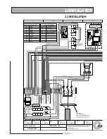
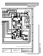
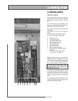
2.2 INSTALLATION
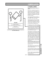
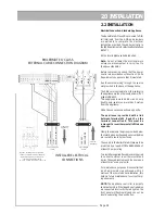
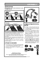
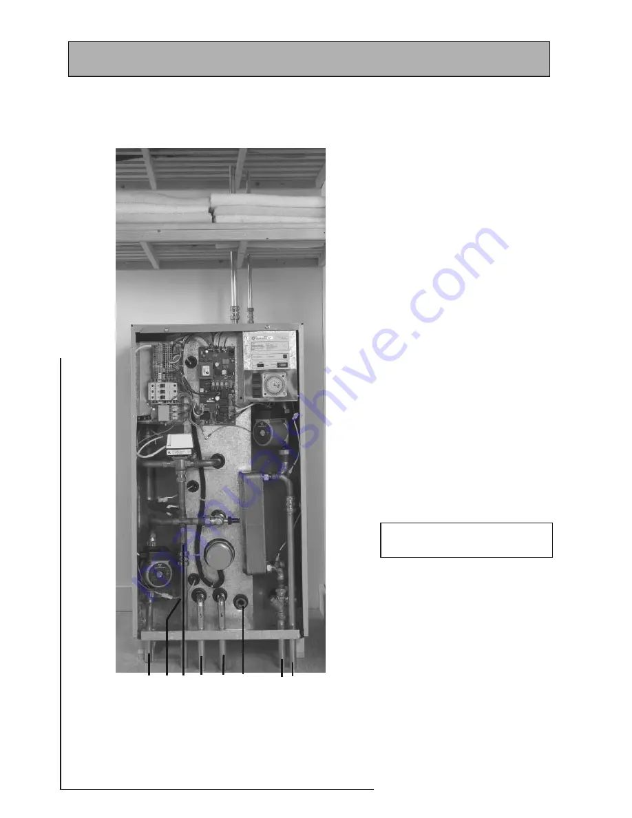
The position of the pipework connections is
shown opposite. The connection sizes and
dimensions are listed in Section 1.2 Technical
Data.
All the connections are also labelled on the
appliance. It is essential that the pipework is
connected to the correct connection.
Connections A, B, D, E and F are plain ended
copper pipe.
Connections C, G and H are compression
fi ttings.
Connection I is RC½ (½ in BSPT internal).
Connection J is a blanked copper pipe.
A - Safety open vent
B - Cold feed/expansion
C - Primary fl ow (from boiler)
D - Primary return (to boiler)
E - Central heating return
F - Central heating fl ow
G - Domestic hot water
H - Incoming mains cold water
I - Drain (valve is not provided with the
appliance)
J - Primary fl ow for pumped summer
towel rail circuit (see page 16)
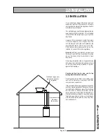
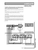
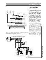
Note: The safety open vent and cold feed/
expansion must be connected to the F & E
cistern using the pipework assembly provided.
Do not alter or connect any pressure-relief
device to the vent pipe of this water heater.
All factory made joints should be checked
after installation in case they have been
loosened during transit.
The fi ttings for the feed and expansion cistern
should be installed following the instructions
provided in a position to suit the particular
location and the cistern fi tted on its supports/
base.
The cold feed/expansion and safety open vent
should be installed between the appliance and
the feed and expansion cistern.
Pipework connections
!
"
#
$
%
&
'
(
)
*
Summary of Contents for BMA 120 SP
Page 44: ...Page 44 ...
Page 45: ...Page 45 BOILERMATE A CLASS SP ...


