


24
GC-1368N
Isocyanate Conditions
Rev. G 6/17/2008
21
Isocyanate Conditions
Material Self-ignition
Moisture Sensitivity of
Isocyanites
Isocyanites (ISO) are catalysts used in two component
foam and polyurea coatings. ISO will react with moisture
(such as humidity) to form small, hard, abrasive crystals,
which become suspended in the fluid. Eventually a film
will form on the surface and the ISO will begin to gel,
increasing in viscosity. If used, this partially cured ISO
will reduce performance and the life of all wetted parts.
To prevent exposing ISO to moisture:
•
Always use a sealed container with a desiccant
dryer in the vent, or a nitrogen atmosphere.
Never
store ISO in an open container.
•
Keep the ISO lube pump reservoir (if installed) filled
with Graco Throat Seal Liquid (TSL), Part 206995.
The lubricant creates a barrier between the ISO and
the atmosphere.
•
Use moisture-proof hoses specifically designed for
ISO, such as those supplied with your system.
•
Never use reclaimed solvents, which may contain
moisture. Always keep solvent containers closed
when not in use.
•
Never use solvent on one side if it has been contam-
inated from the other side.
•
Always lubricate threaded parts with ISO pump oil
or grease when reassembling.
Keep Components A and
B Separate
Foam Resins with 245 fa
Blowing Agents
Some foam blowing agents will froth at temperatures
above 90°F (33°C) when not under pressure, especially
if agitated. To reduce frothing, minimize preheating in a
circulation system.
Spraying materials containing isocyanates creates
potentially harmful mists, vapors, and atomized partic-
ulates.
Read material manufacturer’s warnings and material
MSDS to know specific hazards and precautions
related to isocyanates.
Prevent inhalation of isocyanate mists, vapors, and
atomized particulates by providing sufficient ventila-
tion in the work area. If sufficient ventilation is not
available, a supplied-air respirator is required for
everyone in the work area.
To prevent contact with isocyanates, appropriate per-
sonal protective equipment, including chemically
impermeable gloves, boots, aprons, and goggles, is
also required for everyone in the work area.
Some materials may become self-igniting if applied
too thickly. Read material manufacturer’s warnings
and material MSDS.
The amount of film formation and rate of crystalli-
zation varies depending on the blend of ISO, the
humidity, and the temperature.
NOTICE
To prevent cross-contamination of the equipment’s
wetted parts,
never
interchange component A (isocy-
anate) and component B (resin) parts.
Shut Down Procedure
The purpose of the shut down procedure is to verify
that all critical parts of the system, i.e., the mixing area,
have been checked and cleaned to assure trouble-free
start-up the next time the system is to be operated.
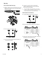
1.
Confirm that both ball valves are in the recirculation
position.
RESIN
CATALYST
If using a filled resin it is suggested that the material
pump and hoses be flushed with a “neat” resin and
that the neat resin is flowing through the system and
exiting the material recirculation hose thoroughly
before shut down procedures are completed.
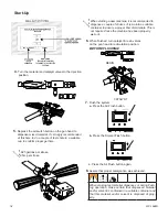
2.
Flush gun head with solvent and air purge
thoroughly.
3.
Material pump should be stopped with pump shaft
in up position and shaft should be cleaned of any
contaminants.
4.
Material pump lube cup should be cleaned of
old lube and refilled with new pump lube.
5.
Material pump should now be cycled so that shaft
is left in down position during shut-down period.
6.
If you are using fillers mixed into the resin, remember on
periods of shut-down, the fillers can settle to the
bottom of the pump and pipe-works.
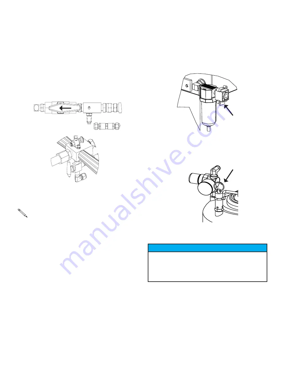
7.
Shut down main air supply by closing yellow lock out
valve.
8.
Slowly bleed the air pressure from the tank by lifting the
ring on the relief valve.
→
Shut-Down
Notice
Failure to cycle Pump Shaft to DOWN position may re-
sult in contaminants to dry or harden on shaft. When the
pump is next operated, severe damage may be done to
upper pump seals.
Summary of Contents for Spartan 3
Page 12: ...12 GC 1368N 4 Push for set up screen Start Up ...
Page 26: ...26 GC 1368N REVISION A 23280 02 SPARTAN 3 ASSEMBLY 01 Assembly Drawings ...
Page 27: ...27 GC 1368N REVISION A 23280 02 SPARTAN 3 ASSEMBLY Assembly Drawings ...
Page 28: ...28 GC 1368N REVISION A 23280 02 SPARTAN 3 ASSEMBLY Assembly Drawings ...
Page 30: ...30 GC 1368N REVISION J 23250 00 SPARTAN 3 CONTROL BOX ASSEMBLY Sub Assembly Drawings ...
Page 31: ...31 GC 1368N REVISION J 23250 00 SPARTAN 3 CONTROL BOX ASSEMBLY Sub Assembly Drawings ...
Page 32: ...32 GC 1368N REVISION J 23250 00 SPARTAN 3 CONTROL BOX ASSEMBLY Sub Assembly Drawings ...
Page 35: ...35 GC 1368N REVISION J 23250 00 SPARTAN CONTROL BOX SCHEMATIC Sub Assembly Drawings ...
Page 43: ...43 GC 1368N REVISION P 23280 00 SPARTAN 3 W PAC ASSEMBLY 01 Accessories ...
Page 44: ...44 GC 1368N REVISION P 23280 00 SPARTAN 3 W PAC ASSEMBLY Accessories ...


