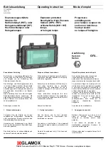


Betriebsanleitung Operating
Instruction Mode
d’emploi
7179601204
Index 05
DCN 22909
5
GLAMOX
Glamox Production GmbH & Co. KG - Glasower Weg 5 - 17166 Teterow – Germany - www.glamox.com/gmo
4.2
Netzanschluss
Nur über Original Kabeleinführung Exe/Exd
gem. ATEX (min. IP67)
Die Befestigungsschrauben des
Anschlussdosendeckel müssen beim
Verschließen mit 2+1Nm angezogen
werden.
Beachten:
Die Klemmung an der Anschluss-
leitung muß sehr sorgfältig durch-
geführt werden.
Im Klemmbereich darf sich keine
Isolierung des Leiters befinden!
Leiter nicht vertauschen
Leiter muß fest angeklemmt sein (bei
Schraubklemmen mit 1,3Nm) und
geprüft werden
Standard
L = Phase - Klemmstellen (1)
N = Neutralleiter - Klemmstellen (2)
PE = Schutzleiter - Klemmstellen (3)
An den Klemmstellen
(1)
bis
(3)
kann
jeweils max. 1 Leiter geklemmt werden. Die
Anschlussklemme ist für folgende
Leitungsquerschnitte geeignet;
flexible Leitungen ohne Aderendhülse
0,5 bis 6,0mm²
starre Leitungen 0,5 bis 6,0mm²
An den Klemmstellen
(5)
ist der Strahler
angeschlossen
4.2
Mains connection
Only original Cable gland Exe/Exd
according ATEX (in. IP67)
The fastening screws of the junction box
cover must be tightened when closing with
2+1 Nm.
Notes:
Connecting of the cable must be done
very carefully
Do not clamp any part of the conductor
insulation!
Do not transpose the conductors
The conductor must be firmly
connected (with 1.3Nm screw
terminals) and tested
L = Phase - Terminal points (1)
N = Neutral conductor -Terminal
points (2)
PE =Protective earth conductor -
Terminal points (3)
Max. 1 conductor can be connected at the
terminal points
(1)
to
(3)
The connection
terminal is suitable for the following line
cross sections;
flexible lines without wire end sleeve
0.5 to 6.0mm²
rigid lines 0.5 bis 6.0mm²
The floodlight is connected at the terminal
points
(5)
.
4.2
Raccordement au secteur
Uniquement par entrée de câble originale
Exe/Exd selon ATEX (min. IP67)
Les vis de fixation du couvercle de la boîte
de jonction doivent être serrées lors de la
fermeture avec 2+1 Nm.
Attention:
Le serrage au câble doit être effectué
avec beaucoup de soin
Ne pas coincer l’isolant du fil
conducteur lors du serrage
Ne pas confondre les fils conducteurs
Les fils conducteurs doivent être
fermement connectés (avec bornes à
vis 1,3Nm) et contrôler
L=Phase-points de raccordement (1)
N = conducteur neutre des points
-terminales (2)
PE = conducteur de protection des
points –terminal (3)
Max. 1 conducteur peut être connecté aux
points terminaux
(1)
à
(3)
La borne de
connexion est adapté pour les sections de
câble suivants;
lignes souples sans embout métallique
0,5 à 6.0mm²
lignes rigides 0,5 bis 6.0mm²
Le projecteur sont connectés aux points
terminaux
(5)
.


