background image

20

Girbau, SA

113432-1

!

!

Gas Information _______________________

It is your responsibility to have all plumbing connections,
materials, and workmanship conform to local and state
regulations or codes of the country of destination.  In the
absence of such codes, all plumbing connections, materials,
and workmanship must conform to the applicable local
requirements.  In the USA this is the National Fuel Gas Code
ANSI Z223.1-LATEST EDITION, or in Canada, the Canadian
Installation Codes CAN/CGA-B149.1-M91 (Natural Gas) or
CAN/CGAB149.2-M91 (L.P. Gas) or LATEST EDITION.

In Australia, the fuel gas code is AS 5601/AG 601, local
authority, gas, electricity, and any other relevant statutory
regulations.

It is important that gas pressure regulators meet applicable
pressure requirements, and that gas meters be rated for the
total amount of all the appliance Btu being supplied.

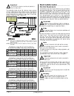
Important

Failure to comply with these codes or ordinances,
and/or the requirements stipulated in this manual,

can result in personal injury and improper operation of the
dryer.

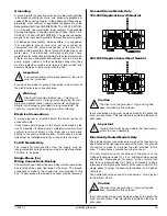
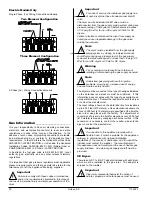
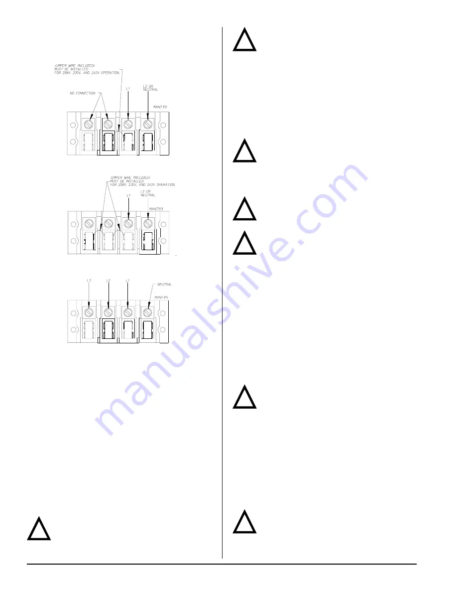
Electric Models Only

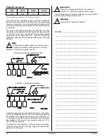
Single-Phase (1ø) Wiring Connections/Hookup

Two Element Configuration

Three Element Configuration

3-Phase (3ø) Wiring Connections/Hookup

!

!

!

Important

For ease of service, the individual gas supply line
of each dryer must have its own manual shutoff

valve.

The dryer and its individual shutoff valve must be
disconnected from the gas supply piping system during any
pressure testing of that system at test pressures in excess
of 1/2 psig (3.5 kPa) for non-CE dryers or 50 mb for CE
dryers.

Failure to isolate or disconnect the dryer from supply as
noted can cause irreparable damage to the gas valve,
voiding the warranty.

Note

The dryer must be isolated from the gas supply
piping system by closing its individual manual

shutoff valve during any pressure test of the gas supply
system at test pressures equal to or less than 1/2 psig (3.5
kPa) for non-CE dryers or 50 mb for CE dryers.

Warning

Fire or explosion could result due to failure of
isolating or disconnecting the gas supply as noted.

Note

Undersized gas piping will result in ignition
problems, slow drying, increased use of energy,

and can create a safety hazard.

The dryer must be connected to the type of heat/gas indicated
on the data label and pressure must be confirmed.  If this
information does not agree with the type of gas available, do
not operate the dryer.  Contact the reseller who sold the dryer
or contact the manufacturer.

The input ratings shown on the data label are for elevations
up to 2,000 feet (610 meters), unless elevation requirements
of over 2,000 feet (610 meters) were specified at the time the
dryer order was placed with the factory.  The adjustment or
conversion of dryers in the field for elevations over 2,000 feet
(610 meters) is made by changing each burner orifice.  If this
conversion is necessary, contact the reseller who sold the
dryer or contact the manufacturer.

Important

If connection to this appliance is made with a
flexible hose, it must be suitable for the appliance

category in accordance with national installation
regulations of the country of destination, and if in doubt the
installer must contact the supplier.  The manufacturer of
this appliance does not recommend the use of flexible gas
supply line/hose.  An external gas supply shutoff must be
provided.

CE Dryers

There is an N.P.T. to B.S.P.T. adaptor included with each dryer,
which must be installed to the gas inlet.  The adaptor is
shipped in the tumbler.

Important

Pipe joint compounds that resist the action of
natural, propane, and butane gases must be used.

!

!

Summary of Contents for SLI14

Page 1: ...SEMENT Assurez vous de bien suivre les instructions données dans cette notice pour réduire au minimum le risque d incendie ou d explosion ou pour éviter tout dommage matériel toute blessure ou la mort Ne pas entreposer ni utiliser d essence ni d autres vapeurs ou liquides inflammables à proximité de cet appareil ou de tout autre appareil QUE FAIRE SI VOUS SENTEZ UNE ODEUR DE GAZ Ne pas tenter d al...

Page 2: ..._____________________________________________________________________ SERIAL NUMBER S ______________________________________________________________________________________ _______________________________________________________________________________________________________ _______________________________________________________________________________________________________ Replacement parts c...

Page 3: ...ircuit s ever be disabled The dryer must never be operated with any of the back guards outer tops or service panels removed Personal injury or fire could result The dryer must never be operated without the lint filter screen in place even if an external lint collection system is used FOR YOUR SAFETY Do not dry mop heads in the dryer Do not use dryer in the presence of dry cleaning fumes The dryers...

Page 4: ...ber and also may be a fire hazard A program should be established for the inspection and cleaning of lint in the burner area exhaust ductwork and area around the back of the dryer The frequency of inspection and cleaning can best be determined from experience at each location Do not operate steam dryers with more than 150 psi 10 34 bar steam pressure Excessive steam pressure can damage the steam c...

Page 5: ...____________ ___________________________________________ ___________________________________________ ___________________________________________ ___________________________________________ ___________________________________________ ___________________________________________ ___________________________________________ ___________________________________________ ___________________________________...

Page 6: ...T 265 lb 120 20 kg AIRFLOW 230 cfm 6 51 cmm EXHAUST CONNECTION DIAMETER 4 10 16 cm COMPRESSED AIR CONNECTION N A COMPRESSED AIR VOLUME N A OVEN SIZE kW Btu hr kcal hr 4 1 13 843 3 488 5 0 17 065 4 300 5 4 18 430 4 644 5 6 19 112 4 816 6 1 20 819 5 246 6 5 22 184 5 590 6 8 23 208 5 848 7 4 25 255 6 364 7 5 25 597 6 450 8 1 27 644 6 966 VOLTAGE AVAILABLE 120 240v 1ø 2w 50 60 Hz APPROXIMATE NET WEIGH...

Page 7: ...113432 1 girbau girbau es 7 SLI9 Specifications _________________________________________________________________ ...

Page 8: ...XIMATE SHIPPING WEIGHT 310 lb 140 61 kg AIRFLOW 360 cfm 10 19 cmm EXHAUST CONNECTION DIAMETER 6 15 24 cm COMPRESSED AIR CONNECTION N A COMPRESSED AIR VOLUME N A OVEN SIZE kW Btu hr kcal hr 7 9 26 962 6 794 8 3 28 327 7 138 9 0 30 716 7 740 11 3 38 566 9 719 12 4 42 320 10 665 12 5 42 661 10 751 13 5 46 074 11 611 VOLTAGE AVAILABLE 120 240v 1ø 2w 50 60 Hz APPROXIMATE NET WEIGHT 305 lb 138 35 kg APP...

Page 9: ...113432 1 girbau girbau es 9 SLI14 Specifications ________________________________________________________________ ...

Page 10: ... INPUT 90 000 Btu hr 22 680 kcal hr EXHAUST CONNECTION DIAMETER 8 20 32 cm COMPRESSED AIR CONNECTION N A COMPRESSED AIR VOLUME N A INLET PIPE CONNECTION 1 2 M N P T 1 2 F B S P T CE ONLY VOLTAGE AVAILABLE 200 416v 1 3ø 3 4w 50 60 Hz APPROXIMATE NET WEIGHT 545 lb 247 21 kg APPROXIMATE SHIPPING WEIGHT 565 lb 256 28 kg AIRFLOW 525 cfm 14 87 cmm EXHAUST CONNECTION DIAMETER 8 20 32 cm COMPRESSED AIR CO...

Page 11: ...113432 1 girbau girbau es 11 SLI23 Specifications ________________________________________________________________ ...

Page 12: ...272 16 kg APPROXIMATE SHIPPING WEIGHT 620 lb 281 23 kg AIRFLOW 560 cfm 15 86 cmm EXHAUST CONNECTION DIAMETER 8 20 32 cm COMPRESSED AIR CONNECTION N A COMPRESSED AIR VOLUME N A OVEN SIZE kW Btu hr kcal hr 18 4 62 763 15 816 20 2 68 975 17 382 20 3 69 418 17 493 20 4 69 521 17 519 22 0 75 084 18 921 VOLTAGE AVAILABLE 120 240V 1ø 2 3w 50 60 Hz APPROXIMATE NET WEIGHT 600 lb 272 16 kg APPROXIMATE SHIPP...

Page 13: ...113432 1 girbau girbau es 13 SLI34 Specifications ________________________________________________________________ ...

Page 14: ...is manual refer to Exhaust Requirements section Important The dryer should be located where a minimum amount of exhaust ducting will be necessary The dryer must be installed with adequate clearance for air openings into the combustion chamber Caution This dryer produces combustible lint and must be exhausted to the outdoors Every 6 months inspect the exhaust ducting and remove any lint buildup Imp...

Page 15: ...ricting passageways or where dryers are located at high altitudes or predominantly low pressure areas Note Component failure due to dry cleaning solvent fumes will void the warranty A 10 inches 25 4 cm B 11 inches 27 94 cm EXAMPLE For a bank of 4 SLI14 dryers 2 unrestricted openings measuring 10 inches by 11 inches 25 4 cm by 27 94 cm are acceptable Important Make up air must be free of dry cleani...

Page 16: ...iance category in accordance with national installation regulations of the country of destination Outside Ductwork Protection To protect the outside end of the horizontal ductwork from the weather a 90 elbow bent downward should be installed where the exhaust exits the building If the ductwork travels vertically up through the roof it should be protected from the weather by using a 180 turn to poi...

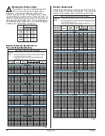
Page 17: ...cordance with electric codes for making all service connections Note The use of aluminum wire will void the warranty An individual ground circuit must be provided to each dryer do not daisy chain Component failure due to improper voltage application will void the warranty The manufacturer reserves the right to make changes in specifications at any time without notice or obligation Important A sepa...

Page 18: ... 6 20 220 1ø 2 8 4 20 230 1ø 2 8 5 20 SLI34 Gas 120 1ø 2 15 6 20 200 1ø 2 10 5 20 208 1ø 2 10 5 20 220 1ø 2 10 0 20 240 1ø 2 9 7 20 220 1ø 2 10 7 20 230 1ø 2 10 8 20 SLI34 Steam 120 1ø 2 14 4 20 200 1ø 2 8 2 20 208 1ø 2 8 2 20 220 1ø 2 7 8 20 240 1ø 2 7 6 20 220 1ø 2 8 4 20 230 1ø 2 8 5 20 1 25 06 ELECTRICAL SERVICE SPECIFICATIONS IMPORTANT NOTES A B C 208 VAC AND 230 240 VAC ARE NOT THE SAME When...

Page 19: ...l wire size must conform to rating of dryer or the dryer can be hard wired directly to the service breaker panel In both cases a strain relief must be installed where the wiring enters the dryer For CE Models Only The means for disconnection from the supply must be incorporated into wiring having a minimum contact separation of 3 0mm in all poles Single Phase 1ø Wiring Connections Hookup The elect...

Page 20: ...dryer must be isolated from the gas supply piping system by closing its individual manual shutoff valve during any pressure test of the gas supply system at test pressures equal to or less than 1 2 psig 3 5 kPa for non CE dryers or 50 mb for CE dryers Warning Fire or explosion could result due to failure of isolating or disconnecting the gas supply as noted Note Undersized gas piping will result i...

Page 21: ...al I2E 1 000 20 40 000 11 72 1 133 M3 H 38 2 578 1 830 25 40 000 11 72 1 365 M3 H 38 2 578 1 Butane I3 3 175 28 30 40 000 11 72 0 845 kg H 52 1 613 1 Propane I3 2 500 37 40 000 11 72 0 845 kg H 52 1 613 1 Butane I3B P 3 175 28 30 50 40 000 11 72 0 845 kg H 49 1 854 1 18 0 Propane I3P 2 500 28 30 50 40 000 11 72 0 845 kg H 49 1 854 1 23 0 Natural I2H I2E 1 000 20 55 000 16 12 1 557 M3 H 22 3 988 1 ...

Page 22: ... ___________________________________________ ___________________________________________ ___________________________________________ ___________________________________________ ___________________________________________ ___________________________________________ ___________________________________________ ___________________________________________ ___________________________________________ ___...

Page 23: ...sconnect the union 3 electrical plugs and the gas train mounting screws from the burner Carefully slide the gas train out of the gas train enclosure The carbon ignitor located at the far end of the gas train is very fragile Remove 2 burner tube mounting screws and remove burner tube in order to gain access to the orifice Using a 3 8 wrench or socket remove the existing orifice and replace it with ...

Page 24: ...crew under vent cap Remove spring under screw and replace with spring from kit P N 140415 Replace regulator adjustment screw Install the gas train back into the dryer gas train enclosure Be sure the tab at the rear of the gas train engages into the mounting slot Connect the union and the 3 electrical plugs Open all shutoff valves reconnect electrical power to the dryer and test for leaks Operate t...

Page 25: ...eter Tighten screw inside the pressure tap or install plug Turn gas cock to ON position and check for leaks with soap solution with main burner ON Steam Information ____________________ It is your responsibility to have all plumbing connections made by a qualified professional to ensure that the steam plumbing installation is adequate and conforms with local state and country regulations or codes ...

Page 26: ... the steam supply header causing the condensate in the line to drain to the header Install a bypass trap in any low point to eliminate wet steam Operating Steam Pressure Model Maximum Heat Input Normal Load Consumption Approx 125 psi 8 6 bar Inlet Return SLI9 150 psig 1 0 MPa 1 2 Bhp 45 lb hr 20 41 kg hr 1 2 1 2 SLI14 150 psig 1 0 MPa 1 75 Bhp 63 lb hr 28 58 kg hr 1 2 1 2 SLI23 150 psig 1 0 MPa 3 ...

Page 27: ...mbler drum by hand to be sure it moves freely Check bolts nuts screws terminals and fittings for tightness and security Check that the vent is connected to the dryer and is exhausted to the outdoors STEAM MODELS Check to ensure all steam shutoff valves are open Preoperational Test ___________________ All dryers are thoroughly tested and inspected before leaving the factory However a preoperational...

Page 28: ... Cycle begins at the end of the heat cycle the L E D display will read COOL DOWN TEMP ___ ___ MINUTES remaining At the end of the heat cycle the dryer will shut off the heat and continue the fan and tumbler until the Cool Down Time or temperature is reached Shutdown Instructions ________________ If the dryer is to be shutdown taken out of service for a period of time the following must be performe...

Page 29: ... lint accumulation from lint chamber thermostat and microprocessor temperature sensor area Warning To avoid the hazard of electrical shock discontinue electrical supply to the dryer Steam Dryers Clean the steam coil fins It is suggested that compressed air and a vacuum cleaner with brush attachment be used Warning When cleaning steam coil fins be careful not to bend the fins If fins are bent strai...

Page 30: ...electric or steam 2 Serial Number Allows the manufacturer to gather information on your particular dryer 3 Type of Heat This describes the type of heat for your particular dryer gas either natural gas or L P gas electric or steam 4 Heat Input For Gas Dryers This describes the heat input in British thermal units per hour Btu hr or kilowatts kW 5 Orifice Size For Gas Dryers Gives the number drill si...

Page 31: ..._____________________ ____________________________________________________________________________________________ ____________________________________________________________________________________________ ____________________________________________________________________________________________ ____________________________________________________________________________________________ ______...

Page 32: ...Part No 113432 1 01 25 06 0 ...

Reviews: