Gilson HM-378 Operating Manual Download Page 7

Gilson Company, Inc. 

Gilson Binder Ignition System:  HM-378

Page 7

•  Once the furnace reaches programmed setpoint 

temperatures, it will maintain these temperatures 
awaiting initiation of a Binder Ignition Test.

• 

The furnace should be preheated for at least one hour 
prior to testing a sample.

7.3  Performing a Typical Binder Ignition Test

1.  Preheat hot-mix asphalt samples in a separate labo-

ratory oven to 100°C to facilitate even distribution of 
the material in the sample basket. Even distribution 
is essential to obtaining good test results.

2.  Insure that a filter is properly installed and is not 

clogged or blinded from previous tests to inhibit air 
flow. Check the filter before each test.

3.  Insure all program settings are correct, as noted 

above.

4.  Remove the pre-heated asphalt sample from the 

laboratory oven and place on the sample basket, 
distributing the material as evenly as possible. Even 
distribution is key to obtaining good test results.

5.  Place the sample basket with sample into the tray, and 

place the cover over the basket. The cover must be 
in place to prevent sample loss and possible damage 
to the elements (see Figure 1 for details on sample 
tray assembly).

WARNING! 

ALWAYS use heat-resistant gloves and a face shield 
when operating the furnace. Long hair should be tied 
back or covered and loose clothing should be secured.

6.  Using the loading fork provided, place the Sample Tray, 

Basket, and Lid assembly into the furnace, centering 
it on the hearth plates. Close the door, checking to be 
sure that the locking pin has engaged the electronic 
door lock mechanism.

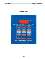
7.  Immediately press the <CONTINUE> key. 

CONT will 

appear on the display. The door will lock automatically 
and the exhaust fan will turn on (if not on already).

WARNING! 

DO NOT FAIL to press the <CONTINUE> key once 
the sample is loaded. If this key is not pressed, the 
sample will begin ignition with the door unlocked. 
The automatic safety door lock will not be activated, 
and DANGER of severe  burns or injury will exist if 
the door is opened.

8.  The display will alternate between 

bo (burn-out set 

point) and the actual main chamber temperature. To 
check after-burner temperature, press <2>.  

AFTb will 

alternate display with the after-burner temperature. 
When the main chamber temperature reaches the 
burn-out setpoint, the display will alternate between 
TEST and the actual main chamber temperature. The 
onset of ignition can be confirmed by observation of 
flames in the chamber 

FROM A DISTANCE via the 

small hole in the front of the chamber.

WARNING! 

NEVER leave the furnace unattended near the end 
of firing! Gilson cannot guarantee the furnace against 
over-firing even though the controller is automatic. 
The operator assumes full responsibility for shutting 
the furnace off at the proper time.

9.  Once ignition occurs, the temperature of the main cham-

ber will rise a minimum of 20°C above burn-out set point 
and is controlled only by the amount of oxygen allowed to 
enter the furnace. During this time the controller cannot 
maintain a constant temperature in the main chamber. 
When ignition is nearing completion, the chamber will 
return to the burn-out set point temperature, and the 
Hold Time timer will begin. The display will alternate 
between 

HOLd and the time remaining. Once the time 

has expired, the door lock will release automatically 
and a beeping alarm will sound. Press <ANY> key 
except <STOP> to silence the alarm. The controller 
will automatically begin to bring the furnace to pre-heat 
conditions in preparation for the next test.

NOTE: If the temperature does not rise at least 
20°C above the burn-out set point, i.e., ignition does 
not occur, the controller will wait 10 minutes before 
proceeding to 

CPLT and unlocking the door.

10.  Carefully remove the Sample Tray Assembly the furnace 

using the fork. Place it on the cooling stand, and remove 
the cover. Check the sample to insure that is free of 
coke. Coke is the solid residual of the binder after all 
volatile material has been removed. If Coke remains, 
replace the cover and return the assembly to the fur-
nace in “PREHEAT” mode until Coke is absent upon 
re-inspection. Adjust program Hold Time for subsequent 
tests as necessary.  Larger sample quantities and larger 
binder contents will require longer Hold Times.

NOTE: If it is necessary to return sample to furnace, 
DO NOT press <CONTINUE>. This will initiate 
another test cycle.

Summary of Contents for HM-378

Page 1: ...Gilson Binder Ignition System HM 378 Rev 02 01 2018 PHONE 800 444 1508 P O Box 200 Lewis Center Ohio 43035 0200 FAX 800 255 5314 740 548 7298 E mail customerservice gilsonco com Website www globalgilson com 740 548 5314 ...

Page 2: ...8 8 0 Custom Applications 8 8 1 Ramp Hold Programming 8 8 2 Delayed Firing Programming 9 9 0 Additional Controller Operating Details 9 10 0 Maintenance 11 10 1 Electrical Problems 11 10 2 Elements 11 10 2 1 Reseating the Elements 11 10 2 2 Replacing Main Chamber Elements 12 10 2 3 Replacing Afterburner Elements 13 10 3 Firebrick Damage 14 11 0 The Temperature Controller Troubleshooting 15 12 0 Rep...

Page 3: ...jury Damage from failure to follow instructions is NOT covered by warranty NOTE READBEFORECONNECTING OPERATING OR SERVICING FURNACE If any questions call Gilson Technical Support at 800 444 1508 1 Place the furnace only on a noncombustible surface positioned no closer than 12in 305mm to any com bustible surface Allow a minimum of 6in 152mm clearance around the unit for proper air circulation 2 Ele...

Page 4: ...tores or can be purchased from Gilson as model HMA 814 The two 10 x 20in Hearth Plates are to be placed on the floor of the main chamber They are designed as a wear ing surface to prevent erosion of the firebrick 1 Place the furnace in a well ventilated covered and protectedarea DONOT storegasoline paintorother flammable liquids in that room 2 Provide a minimum of 12in 305mm clearance be tween the...

Page 5: ...l purpose controller enabling it to also be used for custom Ramp Hold programming as described in Section 8 0 see Figure 1 Times and temperatures in Program 1 have been pro grammed into the controller at the factory The furnace is ready to operate upon installation using this default program To vary temperatures or times re program the controller in the sequence of this sample Values to be program...

Page 6: ...850 Indicates 850 C is setpoint for Afterburner chamber Press ENTER Press ENTER again to accept displayed value or input new exhaust fan activation tem perature then press ENTER CFN 850 Indicates exhaust fan will activate at 850 C After burner temperature Ending display IdLE Programming sequence is complete ready for contin ued operation Action Display Starting display IdLE Press DELAY DELA XX XX ...

Page 7: ...out set point and the actual main chamber temperature To checkafter burnertemperature press 2 AFTbwill alternate display with the after burner temperature When the main chamber temperature reaches the burn out setpoint the display will alternate between TEST and the actual main chamber temperature The onset of ignition can be confirmed by observation of flames in the chamber FROM A DISTANCE via th...

Page 8: ...RT XXXX main chamber temperature Then press ANY key and the display will show IdLE XXXX main chamber temperature The furnace is now shut down The Gilson HM 378 is designed for asphalt binder igni tion tests of asphaltic hot mix to determine binder content percentage in the mix Refer to and follow instructions for that procedure as described in Section 7 0 While the programming procedure described ...

Page 9: ...of the program the furnace will shut off and the display will show CPLT A Operation The first time the furnace is powered the HM 378 controller will display IdLE and the alarm will sound briefly The controller will self test for a period of 10 15 seconds and the display will alternately display IdLE and the Main Chamber temperature B Programming Programming begins from IdLE If the display shows FA...

Page 10: ...emperature When the alarm sounds during a firing shut it off by pressing ANY key except the STOP key If it sounds as soon as the furnace begins firing it is because the alarm was set too low J Setting Alarm During Firing After shutting off the alarm during firing it can be set to go off again later at either a higher or lower temperature To set the alarm during a firing perform these steps 1 When ...

Page 11: ...fuse socket even in a new fuse box Slow Firing The furnace should preheat to desired conditions in one hour or less If not the probable cause is a low voltage supply A minimum of 200V is required If the furnace fires too slowly have the power company check your voltage and readjust transformer if necessary Hot Plug or Outlet If the plug or outlet is hot the probable cause is a defec tive plug or o...

Page 12: ...o stress the wiring c Remove the screws in the element connectors that hold the element lead wires to the element you are replacing d On the same connectors loosen the screws that hold the element and throw old connectors away NOTE ALWAYSusethenewconnectorsfurnished with the new element e Remove and save the porcelain insulators that were under the element connectors f Using long nose pliers remov...

Page 13: ...en the screw Tighten the screw until it squeaks and then tighten some more Cut off twisted end of element even with side of element connectors NOTE Leavingtheexcesselementstickingoutpast element connector could ruin your new element The element can short against something in the switch box As you move the switch box back into place check to see that no wire touches an element connector Wires and w...

Page 14: ...ad some of it Gently stretch it in your hands Avoid stretching only a short portion of the element It is better to distribute the stretch over a longer section Press the element down into the lower part of the groove with a plastic comb or wooden tongue depressor Reinstall the porcelain insula tors Push them flush against the furnace case They protect the element from contact with the case so they...

Page 15: ...s ENTER or removes power from the furnace Upon pressing ENTER the display will alternately show AFT and the temperature in the Afterburner chamber Leave the furnace in this condition for several minutes and note the readings for the Afterburner chamber temperature They should be increasing indicating the Afterburner chamber is getting warmer If the readings are decreasing the thermocouple leads ar...

Page 16: ...tive thermocouple 2 Disconnected thermocouple lead wires 3 Reversed thermocouple lead wires 4 Defective board The controller displays TC2 when the thermocouple tem perature sensor in the firing chamber burns out and FAIL when the thermocouple in the Afterburner chamber burns out Disconnect and lock out power supply Remove the four screws holding the controller faceplate to the switch box Lift the ...

Page 17: ... Afterburner Chamber RPHM 378 12 NEMA 6 50 Receptacle RPHM 378 13 Gaskets top or Bottom 2 Required RPHM 378 14 Gaskets Sides 2 Required RPHM 378 15 Gasket Conversion Kit includes Gaskets and Bracket RPHM 378 16 Door Lock Solenoid RPHM 378 17 Firebrick Repair Compound RPHM 378 18 Exhaust Fan Assembly RPHM 378 19 Door Lock Assembly complete with Housing RPHM 378 20 Adapter Exhaust Fan Adapter Flange...

Page 18: ...Gilson Company Inc Gilson Binder Ignition System HM 378 Page 18 Figure 1 Parts Accessories Diagram ...

Page 19: ...Gilson Company Inc Gilson Binder Ignition System HM 378 Page 19 Control Panel Figure 2 ...

Page 20: ...Gilson Company Inc Gilson Binder Ignition System HM 378 Page 20 Figure 3 Wiring Diagram 208 240V 50 60Hz ...

Page 21: ...en door to load sample heat escapes 4 Close door and start test 5 Burnout temperature programmed by user Could be the same as 2 6 Peak temperature as asphalt ignites and burns off Varies 7 Temperature returns to programmed burnout setting Hold time decoking starts 8 End of hold time Door can be opened sample is removed heat escapes 9 Door is closed 10 Furnace returns to programmed preheat temperat...

Page 22: ... Assembly Main Chamber 2 required one on each side RPHM 378 32 Bottom Firebrick Assembly Main Chamber RPHM 378 38 Firebrick Assembly For Door RPHM 378 33 Back Firebrick Assembly Main Chamber Afterburner Bottom Gilson Binder Ignition Furnace Fire Brick Replacement Assemblies Figure 5 Vent holes to be drilled by installer Main Chamber Top NOTE Ventholesarepredrilled from manufacturer on Top Fire Bri...

Page 23: ...ective under normal and proper use during the specified period providing the furnace has not been subjected to misuse or the listed exclusions Gilson will furnish and install replacement parts at the factory with transportation costs paid by the owner or upon receipt of defective parts at the factory and after factory examination of the defect replacements complete with installation instructions w...

Reviews: