


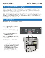


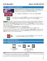


The following verifies that the appliance is receiving power.
1. Be sure the circuit breaker in the electrical panel powering the fryer is
ON
.
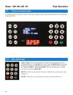
2. Place the
Power Switch
①
in the
[ON]
position. The green
POWER
light
②
should come
ON
and
the controller
③
will power-up. An alarm sounds
and a
“POWER FAILURE”
message is shown on the
Upper Display
. If all of this occurs, return
Power
Switch
to
[OFF]
and continue to
Section 4.3
.
If it does not, refer to
Section 8, Troubleshooting
.
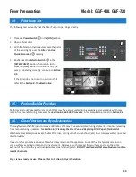
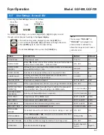
1. Be sure that main gas supply line valve is
OPEN
and that fryer
Gas Valve Handle
is in the
[ON]
position.
2. Heat exchanger ring inside pot should be at ambient temperature. Wipe the ring with a
soaked wet sponge; so that visible moisture remains on the surface.
3. Place
Selector Switch
in the
[COOK]
position. The draft fan should start and you should hear
the ignitor sparking ... burners should light.
NOTE: If burner does not ignite within an allowed time, fryer enters FLAME FAIL error. Return
Selector Switch
to
[OFF], wait 10 seconds and try again
.
4. After ignition, the surface of the heat exchanger should dry quickly (within approximately 15 seconds) and
noticeable heat should be felt rising from the pot, indicating acceptable operation.
4. If burners do not light after two (2) attempts, or appear not to be heating, refer to
Section 8, Troubleshooting
.
5. If the burner system appears to be operational, return
Selector Switch
to
[OFF]
and proceed with the next test as
described in
Section 4.4
..
This test causes the burners to ignite and burn with no oil in Pot. DO NOT allow unit to remain ON for more than
10 seconds. Failure to observe this precaution may result in damage to the heat exchanger.
32
Fryer Preparation
4.2.
Power Test
4.3.
Burner System Test
DO NOT
touch the Heat Exchanger Ring during this test. It becomes very hot and contact may result in severe
burn injury.
1
Model: GGF-400, GGF-720
2
3
The following test will verify that gas burner system is receiving fuel and operating.
Summary of Contents for GGF Series
Page 13: ...4 Model GGF 400 GGF 720 Introduction ...
Page 26: ...Model GGF 400 GGF 720 Overview 18 3 1 Control Panel 5 6 4 3 2 1 7 ...
Page 28: ...20 Model GGF 400 GGF 720 Overview 3 2 Lower Cabinet 5 6 4 3 2 1 7 ...
Page 32: ...24 Model GGF 400 GGF 720 Overview 3 4 Basket and Elevator Assembly 3 1 2 4 ...
Page 38: ...30 Model GGF 400 GGF 720 Overview Notes ...
Page 42: ...34 Fryer Preparation Model GGF 400 GGF 720 ...
Page 80: ...72 Troubleshooting Model GGF 400 GGF 720 ...
Page 88: ...80 Parts List 8 5 Plumbing Model GGF 400 GGF 720 1 2 2 3 3 4 5 6 7 7 7 7 8 10 11 9 12 ...
Page 90: ...82 Parts List 8 6 Basket Basket Cover Model GGF 400 GGF 720 1 2 3 ...
Page 94: ...86 Parts List Notes Model GGF 400 GGF 720 ...
Page 95: ......


