background image


Installation 

Notes before Installation 


The switch isn’t waterproof take care with storage, transportation and operation. 


Position the desktop switch away from water moisture and be sure to provide 

an acceptable temperature and humidity-operating environment. 


Position the switch away from vibrations, dust, direct exposure to sunlight, and strong 

electromagnetic field generators (such as motors

).


Ensure adequate ventilation space around the switch 


Don’t place heavy objects against or upon the switch 


Unplug the switch during electrical thunder storms or power surges 


 Installation Procedures 


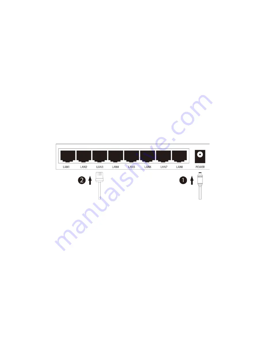
Step 1:

 Connect the supplied power adapter to the Power connector.


1)  All 1-8 LED’s will flash momentarily, which represents resetting of the system. 

2)  The Power LED indicator will light all the time. 

Note: 

If the LED indicators don’t respond as described above, please check the 

connection of power adapter. 


Step 2: 

Connect the network cables to the switch and that’s it 


Summary of Contents for GNS-801G

Page 1: ...User Manual V1 0 Gigacore 8 Port 10 100 1000Mbps Desktop Switch Part number GNS 801G Note Before using your product please read this manual instruction carefully ...

Page 2: ...uction 1 Package Contents 1 Product Overview 1 Front Panel 2 Rear Panel 2 Main Features 1 Installation 3 Notes before Installation 3 Installation Procedures 3 Sample Network Topology 4 Specification 5 CE Mark Warning 6 ...

Page 3: ...e 8 Port Desktop Switch is compatible with any 10 100 1000Mbps Ethernet device The latest innovative energy efficient technologies are implemented making this switch an eco friendly solution for your home or office network saving you up to 75 of the power consumption Main Features Complies with IEEE 802 3 IEEE 802 3u and IEEE 802 3ab standards Eight Auto Negotiation ports provide smart switching b...

Page 4: ...erating at 1000Mbps Off Port is disconnected LED 1 8 Blink Data is transmitting Rear Panel Port Description POWER The Power connector is used in conjunction with the power adapter to power the unit LAN 1 8 Eight Auto Negotiation Ethernet ports used to connect your network devices The working status can be indicated by the corresponding LED s on the front panel ...

Page 5: ...rs such as motors Ensure adequate ventilation space around the switch Don t place heavy objects against or upon the switch Unplug the switch during electrical thunder storms or power surges Installation Procedures Step 1 Connect the supplied power adapter to the Power connector 1 All 1 8 LED s will flash momentarily which represents resetting of the system 2 The Power LED indicator will light all ...

Page 6: ...4 Sample Network Topology Your switch is now fully installed please go ahead with connecting your switch with other network devices Here is a Sample Network Topology for your reference ...

Page 7: ...Ethernet 10 Mbps Half duplex 20Mbps Full duplex Fast Ethernet 100 Mbps Half duplex 200Mbps Full duplex Gigabit Ethernet 2000Mbps Full duplex Hardware Interfaces 8 x 10 100 1000Mbps Auto negotiation Auto MDI MDIX Ethernet Port 1 x Power Connector LED Indicators LAN1 LAN8 Power MAC Address Table 8K Power Supply Input AC 100 240V 50 60Hz Output DC 5V 1A Dimensions W D H 156mm x 90mm x 27mm Others Ope...

Page 8: ...2004 108 EC This is a class B product In a domestic environment this product may cause radio interference in which case the user may be required to take adequate measures Gigacore reserves the right to change specifications without prior notice All brands names and trademarks are property of their respective owners Copyright 2011 Gigacore All rights reserved ...

Reviews: