


8) SATA3 0/1/2/3 (SATA 6Gb/s Connectors)
The SATA connectors conform to SATA 6Gb/s standard and are compatible with SATA 3Gb/s and SATA
1.5Gb/s standard. Each SATA connector supports a single SATA device. The Intel
®
Chipset supports RAID 0,
RAID 1, RAID 5, and RAID 10. Refer to Chapter 3, "Configuring a RAID Set," for instructions on configuring
a RAID array.
Pin No.
Definition
1
GND
2
TXP
3
TXN
4
GND
5
RXN
6
RXP
7
GND
To enable hot-plugging for the SATA ports, refer to Chapter 2, "BIOS Setup," "Peripherals\SATA
And RST Configuration," for more information.
SATA3
0 1
3 2
DEBUG
PORT
G.QBOFM
DEBUG
PORT
G.QBOFM
DEBUG
PORT
G.QBOFM
DEBUG
PORT
G.QBOFM
1
7
7
1
9) M2P/M2M (M.2 Socket 3 Connectors)
The M.2 connectors support M.2 SATA SSDs or M.2 PCIe SSDs and support RAID configuration. Please
note that an M.2 PCIe SSD cannot be used to create a RAID set either with an M.2 SATA SSD or a SATA
hard drive. To create a RAID array with an M.2 PCIe SSD, you must set up the configuration in UEFI BIOS
mode. Refer to Chapter 3, "Configuring a RAID Set," for instructions on configuring a RAID array.
F_USB30
F_ U
B_
F_
F_
_
B
B S_
B
S B_
B
_ S
S_
_
B
_ U
_
B
S
12
3
12
3
12
3
1 2 3
1
1
1
1
B S S
S
_S
S
S
U
1
2
3
4
5
S
3
B S S
S
U
_ _
3
F_USB3 F
S
_
S
_
S
_
S F
B_
B_
F
_ 0
S
S
_ 0
F
_ F
_
_
_
_B
U
S
_S
_
S F_
USB 0_ B
B_
F_USB3
F_USB30 3
_
_3
U
S _
80
60
F_USB30
F_ U
B_
F_
F_
_
B
B S_
B
S B_
B
_ S
S_
_
B
_ U
_
B
S
12
3
12
3
12
3
1 2 3
1
1
1
1
B S S
S
_S
S
S
U
1
2
3
4
5
S
3
B S S
S
U
_ _
3
F_USB3 F
S
_
S
_
S
_
S F
B_
B_
F
_ 0
S
S
_ 0
F
_ F
_
_
_
_B
U
S
_S
_
S F_
USB 0_ B
B_
F_USB3
F_USB30 3
_
_3
U
S _
80
60
42
M2P
M2M
(Note)
Follow the steps below to correctly install an M.2 SSD in the M.2 connector.
Step 1:
Use a screwdriver to unfasten the screw on the heatsink and then remove the heatsink first. (Only the M2P
connector has the heatsink.) If you want to install an M.2 2242 or 2260 SSD, get a screw and a standoff
from the included M.2 screw kit and follow the pictures below to install.
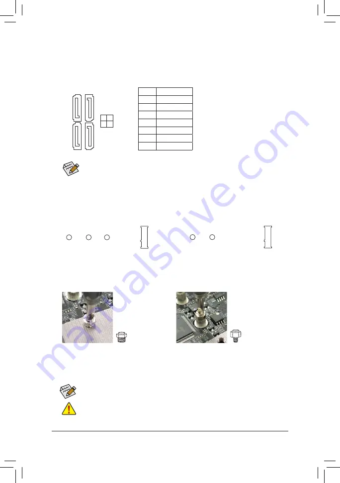
1. 2242 size:
Fasten standoff A to the "42"
hole on the PCH heatsink.
2. 2260 size:
Fasten standoff B to the "60"
hole on the motherboard.
Step 2:
Slide the M.2 SSD into the connector at an angle.
Step 3:
Press the M.2 SSD down and then secure it with the screw. Replace the heatsink and secure it to the
original hole.
Standoff A
Standoff B
Select the proper hole for the M.2 SSD to be installed and refasten the screw and standoff.
If you want to install an M.2 2260 or 2280 SSD, be sure not to fasten standoff A to the heatsink, or
the M.2 SSD may be damaged.
- 16 -
(Note) The M2M connector is on the back of the motherboard.


