background image

- 39 -

BIOS Setup

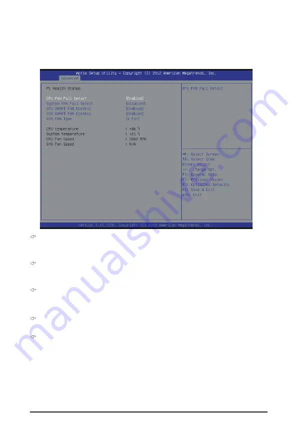
2-2-4  H/W Monitor

Press Enter to view the Hardware Monitor screen which displays a real-time record of the CPU/system 
temperature, and fan speed, The related system voltage and temperature items on this window are non-

configurable.

  CPU/System FAN Fail Detect


Enable CPU/System Fan Stop Warning function.


Option available: Enabled/Disabled. Default setting is 

Enabled

.

  CPU/System SMART FAN Control


Enable CPU/System Smart Fan function.


Option available: Enabled/Disabled. Default setting is 

Enabled

.

  SYS FAN Type


Select system fan type.


Option available: 3 Pin/4 Pin. Default setting is 

4 Pin

.

  CPU/System Temperature


Displays current CPU and system temperature.

  CPU/System Fan Speed (RPM)


Displays current CPU and system fan speed.

Summary of Contents for MSH87DI-SI

Page 1: ...MSH87DI SI LGA1155 socket motherboard for Intel Core i3 Core i5 Core i7 processors Intel Pentium series processors User s Manual Rev 1001 ...

Page 2: ...d features in this manual may be made by GIGABYTE without prior notice No part of this manual may be reproduced copied translated transmitted or published in any form or by any means without GIGABYTE s prior written permission Documentation Classifications Inordertoassistintheuseofthisproduct GIGABYTEprovidesthefollowingtypesofdocumentations For detailed product information carefully read the User...

Page 3: ... 1 Dual Channel Memory Configuration 14 1 4 2 Installing a Memory 15 1 5 Back Panel Connectors 16 1 6 Internal Connectors 18 Chapter 2 BIOS Setup 30 2 1 The Main Menu 32 2 2 Advanced Menu 34 2 2 1 CPU Configuration 35 2 2 2 SATA Configuration 37 2 2 3 Intel R Rapid Start Technology 38 2 2 4 H W Monitor 39 2 2 5 Intel R Smart Connect Technology 40 2 2 6 Intel R Thunderbolt 41 2 3 Chipset Menu 43 2 ...

Page 4: ... Two SATA cables I O Shield The box contents above are for reference only and the actual items shall depend on the product package you obtain The box contents are subject to change without notice The motherboard image is for reference only ...

Page 5: ... 5 MSH87DI SI Motherboard Layout 3 4 2 1 5 7 10 11 12 13 14 15 16 18 17 19 21 22 23 24 25 26 27 28 29 30 31 32 33 34 35 37 36 20 8 9 6 ...

Page 6: ...r 18 SATAIII_0 SATA 6Gb s cable connector 19 SATA_PWR Hard disk power connector 20 CPU_FAN CPU fan connector 21 SYS_PANEL Front panel header 22 MON_NOW Monitor power switch header 23 SO_DIMM2 DDR3 SO DIMM slot channel 2 1 24 SO_DIMM1 DDR3 SO DIMM slot channel 1 1 25 LVDS_PWR LVDS power select jumper 3V 5V 26 LVDS LVDS connector 27 LVDS_EN DIS LVDS Eeable Disable jumper 28 FPD Flat Panel Display co...

Page 7: ...y and first touch a metal object to eliminate static electricity Prior to installing the motherboard please have it on top of an antistatic pad or within an electrostatic shielding container Before unplugging the power supply cable from the motherboard make sure the power supply has been turned off Before turning on the power make sure the power supply voltage has been set according to the local v...

Page 8: ...dio 2 4 5 1 7 1 Channel LAN 1 x Realtek RTL8111G supports 10 100 1000 Mbps Expansion Slots 1 x Mini PCI Express x4 slot Half size Supports 25W Only 1 x mSATA slot Full size For mSATA Onboard Graphics Build in Intel processor Storage Interface 2 x SATA 6Gb s connectors USB 4 x USB 3 0 ports back panel 3 x USB 2 0 headers Card reader Touch panel and other devices Internal Connectors 1 x 2 pin power ...

Page 9: ... 1 x HDMI port 1 x Thunderbolt port 4 x USB 3 0 ports 1 x Audio MIC In 1 x Audio Line Out I O Controller iTE IT8773 chip Hardware Monitor CPU System temperature detection CPU fan speed detection BIOS 1 x 64 Mbit flash AMI BIOS Form Factor Mini ITX Form Factor 170cm x 170cm ...

Page 10: ...nment keys on the CPU socket Apply an even and thin layer of thermal grease on the surface of the CPU Do not turn on the computer if the CPU cooler is not installed otherwise overheating and damage of the CPU may occur Set the CPU host frequency in accordance with the CPU specifications It is not recommended that the system bus frequency be set beyond hardware specifications since it does not meet...

Page 11: ...e other to lightly replace the load plate When replacing the load plate make sure the front end of the load plate is under the shoulder screw NOTE Hold the CPU socket lever by the handle not the lever base portion Step 2 Remove the CPU socket cover as shown Hold your index finger down on the rear grip of the socket cover and use your thumb to lift up the front edge next to the REMOVE mark and then...

Page 12: ...ng the cooler note the direction of the arrow sign on the male push pin Turning the push pin along the direction of the arrow is for removing the cooler and the opposite direction is for installing it Step 3 Place the cooler atop the CPU aligning the four push pins through the pin holes on the motherboard Push down on the push pins diagonally Step 4 You should hear a click when pushing down each p...

Page 13: ...n off the computer and unplug the power cord from the power outlet before installing the memory to prevent hardware damage Memory modules have a foolproof design A memory module can be installed in only one direction If you are unable to insert the memory switch the direction Due to CPU limitations read the following guidelines before installing the memory in Dual Channel mode 1 Dual Channel mode ...

Page 14: ... sure to install DDR3 DIMMs on this motherboard Installation Step Step 1 Align the memory with the DIMM module and insert the DIMM memory module into the DIMM slot Please note that memory module has a foolproof insertion design A memory module can be installed In only one direction Step 2 Push down the memory and seat it firmly Step 3 Reverse the installation steps when you wish to remove the DIMM...

Page 15: ... in BIOS Setup The two Thunderbolt ports support two DisplayPort monitors in total The two DisplayPort monitors that are daisy chained to the same port must be separated by a Thunderbolt device The maximum supported resolution is 3840x2160 but the actual resolutions supported are dependent on the monitor being used Line Out Front Speaker Out Green The default Line Out Front Speaker Out jack Stereo...

Page 16: ...aight out from the connector Do not rock it side to side to prevent an electrical short inside the cable connector Activity LED Connection Speed LED LAN Port Activity LED Connection Speed LED State Description Orange 1 Gbps data rate Green 100 Mbps data rate Off 10 Mbps data rate State Description Blinking Data transmission or receiving is occurring Off No data transmission or receiving is occurri...

Page 17: ...d from the power outlet to prevent damage to the devices After installing the device and before turning on the computer make sure the device cable has been securely attached to the connector on the motherboard 1 SYS_PANEL 2 AD_IN 3 SATAIII_0 4 SATAIII_1 5 FUSB2_3 6 FUSB2_2 7 FUSB2_4 8 FUSB3_1 9 WEB_CON 10 CPU_FAN 11 SYS_FAN 12 SPKR 13 FP_AUDIO 14 DMIC_CON 15 FPD 16 MON_SW 17 LVDS 18 BATTERY 19 CLR...

Page 18: ... SYS_PANEL Front Panel Header Connect the power switch reset switch speaker chassis intrusion switch sensor and system status indicator on the chassis to this header according to the pin assignments below Note the positive and negative pins before connecting the cables Pin No Signal Name Definition 1 HD Hard Disk LED Signal anode 2 MPD Power LED Signal anode 3 HD Hard Disk LED Signal cathode 4 MPD...

Page 19: ...tors conform to SATA 6Gb s standard and are compatible with SATA 3Gb s standard Each SATA connector supports a single SATA device Pin No Definition 1 GND 2 TXP 3 TXN 4 GND 5 RXN 6 RXP 7 GND 1 7 DEBUG PORT 2 AD_IN 2 Pin Power Connector 1 2 Pin No Definition 1 GND 2 19V SATAIII_0 SATAIII_1 ...

Page 20: ...can provide two USB ports via an optional USB bracket For purchasing the optional USB bracket please contact the local dealer 10 9 2 1 Pin No Definition 1 VCC 2 VCC 3 USB 4 USB 5 USB 6 USB 7 GND 8 GND 9 No Pin 10 NC 6 7 FUSB2_3 FUSB2_4 USB 2 0 Headers 5 1 FUSB2_2 FUSB2_4 Pin No Definition 1 VCC 2 USB 3 USB 4 GND ...

Page 21: ... IntA_P2_SSTX 15 IntA_P2_SSTX 16 GND 17 IntA_P2_SSRX 18 IntA_P2_SSRX 19 Power 20 No Pin 8 FUSB3_1 USB 3 0 Header The headers conform to USB 3 0 specification Each USB header can provide two USB ports via an optional USB bracket For purchasing the optional USB bracket please contact the local dealer 1 20 1011 1 5 9 WEB_CON WebCAM Header Pin No Definition 1 Power 2 USB D 3 USB D 4 GND 5 NC ...

Page 22: ...hich requires the use of a CPU fan with fan speed control design For optimum heat dissipation it is recommended that a system fan be installed inside the chassis Be sure to connect fan cables to the fan headers to prevent your CPU and system from overheating Overheating may result in damage to the CPU or the system may hang These fan headers are not configuration jumper blocks Do not place a jumpe...

Page 23: ...work or even damage it Pin No Definition 1 F_MIC_L 2 GND 3 F_MIC_R 4 GPIO_DET 5 F_LINE_R 6 F_MIC_JD 7 GND 8 No Pin 9 F_LINE_L 10 F_LINE_JD The front panel audio header supports HD audio by default Audio signals will be present on both of the front and back panel audio connections simultaneously Some chassis provide a front panel audio module that has separated connectors on each wire instead of a ...

Page 24: ...ter monitor or LCD television set to the display panel Most laptops LCD computer monitors and LCD TVs use this interface internally The headers conform to FPD specification Pin No Definition 1 Backlight Enable 2 Backlight control 3 FPD_19V 4 FPD_19V 5 GND 6 GND 7 Brighrness Up 8 Brighrness Down Pin No Definition 1 Control 3 3V 2 GND 1 1 8 2 16 MON_SW Monitor Power Switch header ...

Page 25: ...3_P 2 ODD_Lane3_N 3 ODD_Lane2_P 4 ODD_Lane2_N 5 ODD_Lane1_P 6 ODD_Lane1_N 7 ODD_Lane0_P 8 ODD_Lane0_N 9 EVEN_Lane3_P 10 EVEN_Lane3_N 11 EVEN_Lane2_P 12 EVEN_Lane2_N 13 EVEN_Lane1_P 14 EVEN_Lane1_N 15 EVEN_Lane0_P 16 EVEN_Lane0_N 17 GND 18 LCD_VCC 19 LCD_VCC 20 LCD_VCC Pin No Definition 21 NC 22 EDID_3 3V 23 GND 24 LVDS_SENSE 25 NC 26 ODD_CLK_P 27 ODD_CLK_N 28 GND 29 GND 30 GND 31 EDID_CLK 32 BLKT_...

Page 26: ...ion Default setting Close Clear CMOS data Always turn off your computer and unplug the power cord before replacing the battery Replace the battery with an equivalent one Danger of explosion if the battery is replaced with an incorrect model Contact the place of purchase or local dealer if you are not able to replace the battery by yourself or uncertain about the battery model Used batteries must b...

Page 27: ...28 20 LVDS_PWR LVDS Power Select Jumper 21 LVDS_EN DIS LVDS Enable Disable Jumper 1 1 1 2 Close Set to 3V 2 3 Close Set to 5V Default setting 1 1 1 2 Close Enable LVDS funciton Default setting 2 3 Close Disable LVDS funciton ...

Page 28: ... 29 Hardware Installation 22 BL_SW Back Light Switch The Back Light switch provides the function for screen back light adjustment Pin No Definition 1 BL_DOWN 2 BL_UP 1 2 ...

Page 29: ... with caution Inadequate BIOS flashing may result in system malfunction It is recommended that you not alter the default settings unless you need to to prevent system instability or other unexpected results Inadequately altering the settings may result in system s failure to boot If this occurs try to clear the CMOS values and reset the board to default values Refer to the Restore Defaults section...

Page 30: ...ation of boot sequence Security Change set or disable supervisor and user password Configuration supervisor password allows you to restrict access to the system and BIOS Setup A supervisor password allows you to make changes in BIOS Setup A user password only allows you to view the BIOS settings but not to make changes Save Exit Save all the changes made in the BIOS Setup program to the CMOS and e...

Page 31: ... displayed on the bottom line of the Main Menu Submenu Help While in a submenu press F1 to display a help screen General Help of function keys available for the menu Press Esc to exit the help screen Help for each item is in the Item Help block on the right side of the submenu When the system is not stable as usual select the Restore Defaults item to set your system to its defaults The BIOS Setup ...

Page 32: ...utility was created LAN MAC Address Displays the MAC address information Memory Information Size Determines how much total memory is present during the POST Frequency Display the memory frequency information ME FW Version Display the ME firmware version System Date Set the date following the weekday month day year format System Time Set the system time following the hour minute second format ...

Page 33: ... Setup 34 2 2 Advanced Menu The Advanced menu display submenu options for configuring the function of various hardware components Select a submenu item then press Enter to access the related submenu screen ...

Page 34: ...he Displays the technical specifications for the installed processor Intel Virtualization Technology Select whether to enable the Intel Virtualization Technology function VT allows a single platform to run multiple operating systems in independent partitions Options available Enabled Disabled Default setting is Enabled EIST Enhanced Intel SpeedStep Technology Conventional Intel SpeedStep Technolog...

Page 35: ...ption The C3 C6 state is a more enhanced power saving state than C1 Options available Enabled Disabled Default setting is Enabled CPU C7 Report Note Allows you to enable or disable the CPU C7 ACPI C3 report Options available Disabled CPU C7 CPU C7s Default setting is CPU C7s Note This item is present only if you install a CPU that supports this feature For more information about Intel CPUs unique ...

Page 36: ...The category identifies Serial ATA and mSATA types of hard disk that are installed in the computer System will automatically detect HDD type Note that the specifications of your drive must match with the drive table The hard disk will not work properly if you enter improper information for this category Hard drive information should be labeled on the outside device casing Enter the appropriate opt...

Page 37: ...abled Disabled Default setting is Enabled Entry After If enabled will allow you to set a timer to wake the computer at a particular interval Option available 10 minutes Default setting is 10 minutes Active Page Threshold Support If enabled the system will support RST with small partition Option available Enabled Disabled Default setting is Disabled Hybird Hard Disk Support Enable Disable Hybird Ha...

Page 38: ...l Detect Enable CPU System Fan Stop Warning function Option available Enabled Disabled Default setting is Enabled CPU System SMART FAN Control Enable CPU System Smart Fan function Option available Enabled Disabled Default setting is Enabled SYS FAN Type Select system fan type Option available 3 Pin 4 Pin Default setting is 4 Pin CPU System Temperature Displays current CPU and system temperature CP...

Page 39: ...IOS Setup 40 2 2 5 Intel R Smart Connect Technology Intel R Smart Connect Technology Enable Disable Intel R Smart Connect Technology function Option available Enabled Disabled Default setting is Disabled ...

Page 40: ...y level Option available Unique ID Legacy Mode DP only Default setting is Unique ID Wake From Thunderbolt Devices Option available Enabled Disabled Default setting is Enabled AIC Support Option available Enabled Disabled Default setting is Disabled Thunderbolt PCIe Cache line Size Configure Thunderbolt PCIe Cache line Size Option available 0 1 2 4 8 6 32 64 128 Default setting is 32 SMI Notify Sup...

Page 41: ...ption Rom Option available Enabled Disabled Default setting is Enabled Thunderbolt SwSMI Delay Press keys to increase or decrease the desired values Reserved Mem per phy slot Press keys to increase or decrease the desired values Reserved PMem per phy slot Press keys to increase or decrease the desired values TBT Device ID resource Support Option available Enabled Disabled Default setting is Disabl...

Page 42: ...e mode of operation if an AC power loss occurs Power On System power state when AC cord is re plugged Power Off Do not power on system when AC power is back Last State Set system to the last sate when AC power is removed Options available Power On Power Off Last State Default setting is Power Off Onboard LAN Device Enable Disable onboard LAN controller Options available Enabled Disabled Default se...

Page 43: ...Intel ME firmware update procedure please see the following section 2 3 1 Intel ME Firmware Update Procedure Intel ME Firmware Update Procedure 1 Boot up your system and enter the BIOS setup screen 2 Select Chipset menu select Intel ME FW Update and set this item to Enabled 3 Save and reset system 4 System rebooting automatically and re enter the BIOS setup screen 5 Press power button to power off...

Page 44: ... priority during system boot up BIOS setup will display an error message if the drive s specified is not bootable Boot Configuration Boot Option Priorities Boot Option 1 Press Enter to configure the boot priority CSM parameters Press Enter to configure the advanced items ...

Page 45: ... Options available Do not launch UEFI only Legacy only Legacy first UEFI first Default setting is UEFI Only Launch Storage OpROM policy Determines which devices system will boot to Options available Do not launch UEFI only Legacy only Legacy first UEFI first Default setting is Legacy only Other PCI device ROM priority For PCI devices other than Network Mass storage or Video device defines which Op...

Page 46: ... 47 BIOS Setup Network stack Enable Disable UEFI network stack Options available Enabled DIsabled Default setting is Disabled ...

Page 47: ...orPassword Press Enter to configure the Administrator password User Password Press Enter to configure the user password Secure Boot Display the Secure Boot State Secure Boot Control Secure Boot requires all the applications that are running during the booting process to be pre signed with valid digital certificates This way the system knows all the files being loaded before Windows 8 loads and get...

Page 48: ...Boot Mode Define the Secure Boot Mode Option available Standard Custom Default setting is Standard Key Management Note Press Enter for configuration of advanced items Note Advanced items prompt when this item is set to Cutom ...

Page 49: ...led Disabled Default setting is Disabled Install Default Secure Boot Keys Press Enter to install all factory default keys Save All Secure Boot Variables Press Enter to save all Secure Boot Variables Platform Key PK Display the status of Platform Key Delete the PK Press Enter to delete the existed PK Once the PK is deleted all the system s Secure Boot keys will not be activated Set new PK File Pres...

Page 50: ...atabase Delete DB Press Enter to delete the db from your system Set new DB Press Enter to configure a new db Append aVar to DB Press Enter to load additional db from a storage devices Forbidden Signature Database DBX Display the status of Forbidden Signature Database Delete the DBX Press Enter to delete the dbx from your system Set DBX from File Press Enter to configure a new dbx Append Var to DBX...

Page 51: ...ade and close the BIOS setup and reset the system Options available Yes No Discard Changes and Reset Discards changes made and close the BIOS setup and reset the system Options available Yes No Restore Defaults Press Enter on this item and then press the Y key to load the default BIOS settings Options available Yes No Boot Override Press Enter to configure the device as the boot up drive ...

Reviews: