background image

- 11 -

Hardware Installation

1-3  Installing the CPU and CPU Cooler

1-3-1  Installing the CPU

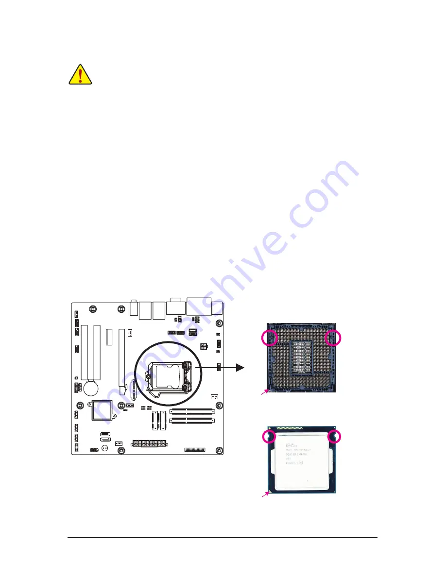
A.  Locate the alignment keys on the motherboard CPU socket and the notches on the CPU.

Read the following guidelines before you begin to install the CPU:  

• 

Make sure that the motherboard supports the CPU.

• 

Always turn off the computer and unplug the power cord from the power outlet before installing 
the CPU to prevent hardware damage.

• 

Locate the pin one of the CPU. The CPU cannot be inserted if oriented incorrectly. (Or you may 
locate the notches on both sides of the CPU and alignment keys on the CPU socket.)

• 

Apply an even and thin layer of thermal grease on the surface of the CPU.

• 

Do not turn on the computer if the CPU cooler is not installed, otherwise overheating and 
damage of the CPU may occur.

• 

Set the CPU host frequency in accordance with the CPU specifications. It is not recommended 
that the system bus frequency be set beyond hardware specifications since it does not meet the 

standard requirements for the peripherals. If you wish to set the frequency beyond the standard 
specifications, please do so according to your hardware specifications including the CPU, 
graphics card, memory, hard drive, etc.

Notch

Alignment Key

Alignment Key

Notch

LGA1155 CPU

LGA1155 CPU Socket

Pin One Corner of the CPU Socket

Triangle Pin One Marking on the CPU

Summary of Contents for MATMH61

Page 1: ...MATMH61 Intel Socket LGA1155 processor motherboard User s Manual Rev 1201...

Page 2: ...d features in this manual may be made by GIGABYTE without prior notice No part of this manual may be reproduced copied translated transmitted or published in any form or by any means without GIGABYTE...

Page 3: ...dvanced Menu 36 2 2 1 ACPI Settings 37 2 2 2 S5 RTC Wake Settings 38 2 2 3 Trusted Computing Optional 39 2 2 4 CPU Configuration 40 2 2 5 SATA Configuration 42 2 2 6 USB Configuration 43 2 2 7 H W Mon...

Page 4: ...CD Two SATA cables I O Shield The box contents above are for reference only and the actual items shall depend on the product package you obtain The box contents are subject to change without notice T...

Page 5: ...5 MATMH61 Motherboard Layout 1 2 3 4 6 7 8 9 11 10 5 12 13 14 15 16 17 19 18 20 21 22 32 23 24 25 26 27 28 29 30 31 33 34 35 37 36 38 39 41 40 43 44 45 46 47 48 49 50 51 52 42...

Page 6: ...m connectors 13 JCOM6 COM9 Power Select jumper 14 COM9 Serial port cable connector 9 15 JCOM8 COM10 Power Select jumper 16 ATX_12V 4 pin power connector 17 COM10 Serial port cable connector 10 18 CPU...

Page 7: ...LPC LPC connector 42 CI Case open intrusion header 43 CLR_CMOS Clear CMOS jumper 44 COM1 Serial port cable connector 1 45 COM2 Serial port cable connector 2 46 F_AUDIO Front audio header 47 SPK_OUT A...

Page 8: ...and first touch a metal object to eliminate static electricity Prior to installing the motherboard please have it on top of an antistatic pad or within an electrostatic shielding container Before unp...

Page 9: ...p to 10 USB 2 0 1 1 ports 4 on the back panel 6 via the USB brackets connected to the internal USB headers Internal Connectors 1 x 4 pin ATX 12V power connector 1 x 24 pin ATX main power connector 2 x...

Page 10: ...nges to the product specifications and product related information without prior notice Hardware Monitor System voltage detection CPU System temperature detection CPU System fan speed control Whether...

Page 11: ...ment keys on the CPU socket Apply an even and thin layer of thermal grease on the surface of the CPU Do not turn on the computer if the CPU cooler is not installed otherwise overheating and damage of...

Page 12: ...other to lightly replace the load plate When replacing the load plate make sure the front end of the load plate is under the shoulder screw NOTE Hold the CPU socket lever by the handle not the lever...

Page 13: ...g the cooler note the direction of the arrow sign on the male push pin Turning the push pin along the direction of the arrow is for removing the cooler and the opposite direction is for installing it...

Page 14: ...hardware damage Memory modules have a foolproof design A memory module can be installed in only one direction If you are unable to insert the memory switch the direction 1 4 1 Installing a Memory Ins...

Page 15: ...USB flash drive and etc Line In Jack Blue The default line in jack Use this audio jack for line in devices such as an optical drive walkman etc Line Out Jack Green The default line out jack Use this a...

Page 16: ...COM6 14 COM7 15 COM8 16 COM9 17 COM10 18 JCOM6 19 JCOM8 20 F_AUDIO 21 JCOM3 JRS14 JRS15 JRS21 JRS19 22 JCOM5 JRS23 JRS22 JRS27 JRS29 23 SPK_OUT 24 BKL_CN 25 LPT 26 F_PANEL 27 LVDS 28 JRS9 29 JRS10 30...

Page 17: ...connectors you wish to connect Before installing the devices be sure to turn off the devices and your computer Unplug the power cord from the power outlet to prevent damage to the devices After insta...

Page 18: ...rientation The 12V power connector mainly supplies power to the CPU If the 12V power connector is not connected the computer will not start To meet expansion requirements it is recommended that a powe...

Page 19: ...d SATA1 SATA1 SATA2 SATA2 4 5 6 CPU_FAN SYS_FAN CPU Fan System Fan Headers The motherboard has one 4 pin CPU fan header CPU_FAN and two 4 pin SYS_FAN system fan headers Most fan headers possess a fool...

Page 20: ...M CLR_PWD IR COMB SPDIF_IO F1_1394 F2_1394 GAME SMB_CONN F_ NE 1 9 2 10 F_USB1 Pin No Definition 1 Power 5V 2 Power 5V 3 USBP9 4 USBP8 5 USBP9 6 USBP8 7 GND 8 GND 9 No Pin 10 NC Pin No Definition 1 Po...

Page 21: ...NDTR2 4 NTXD2 5 NDSR2 6 GND 7 NCTS2 8 NRTS2 9 NC 10 NRI2 Pin No Definition 1 NRXD8 2 NDCD8 3 NDTR8 4 NTXD8 5 NDSR8 6 GND 7 NCTS8 8 NRTS8 9 NC 10 NRI8 Pin No Definition 1 NRXD5 2 NDCD5 3 NDTR5 4 NTXD5...

Page 22: ...1 F_AUDIO Front Panel Audio Header The front panel audio header supports Intel High Definition audio HD and AC 97 audio You may connect your chassis front panel audio module to this header Make sure t...

Page 23: ...RS485 Select Header for Serial Port 3 Pin No Definition 1 RXD232 2 RXD3 3 RXD422 4 RXD3 5 RXD485 6 RXD3 1 2 Close RS422 RS485 1 2 Close RS232 3 4 Close RS422 5 6 Close RS485 2 3 Close RS232 Default s...

Page 24: ...RS485 Select Header for Serial Port 4 41 42 JCOM5 JRS23 JRS22 JRS27 JRS29 Pin No Definition 1 RXD232 2 RXD4 3 RXD422 4 RXD4 5 RXD485 6 RXD4 1 2 Close RS422 RS485 1 2 Close RS232 3 4 Close RS422 5 6 Cl...

Page 25: ...re Installation 23 SPK_OUT Audio Amplifier Connector 24 BLK_CN LCD Inverter Connector 41 42 41 42 5 4 1 1 Pin No Definition 1 OUT_R 2 OUT_R 3 OUT_L 4 OUT_L Pin No Definition 1 VCC 2 PWM_OUT 3 ENABKL 4...

Page 26: ...1 2 29 30 Pin No Definition Pin No Definition 1 STB 16 GND 2 PD3 17 PD1 3 GND 18 PD7 4 GND 19 GND 5 AFD 20 GND 6 PD4 21 INIT 7 GND 22 ACK 8 GND 23 GND 9 PD0 24 GND 10 PD5 25 PD2 11 GND 26 BUSY 12 GND...

Page 27: ...er by chassis A front panel module mainly consists of power switch reset switch power LED hard drive activity LED speaker and etc When connecting your chassis front panel module to this header make su...

Page 28: ...c interface standard for high speed data transmission Pin No Definition Pin No Definition 1 VCC3 21 A5P_C 2 VCC 22 A4P_C 3 VCC3 23 A5M_C 4 VCC 24 A4M_C 5 SPC0 25 GND 6 SPD0 26 GND 7 GND 27 A7P_C 8 GND...

Page 29: ...as BIOS configurations date and time information in the CMOS when the computer is turned off Replace the battery when the battery voltage drops to a low level or the CMOS values may not be accurate or...

Page 30: ...place a jumper cap on the two pins to temporarily short the two pins or use a metal object like a screwdriver to touch the two pins for a few seconds 35 CI Case Open Intrusion Header This motherboard...

Page 31: ...Hardware Installation 31 36 GPIO_CNT GPIO Connector 1 11 2 12 Pin No Definition 1 GPIO1 2 GPIO68 3 GPIO6 4 GPIO69 5 GPIO7 6 GPIO70 7 GPIO17 8 GPIO71 9 SMBCLK 10 SMBDATA 11 VCC 12 GND...

Page 32: ...with caution Inadequate BIOS flashing may result in system malfunction It is recommended that you not alter the default settings unless you need to to prevent system instability or other unexpected re...

Page 33: ...Security Change set or disable supervisor and user password Configuration supervisor password allows you to restrict access to the system and BIOS Setup A supervisor password allows you to make chang...

Page 34: ...le in a submenu press F1 to display a help screen General Help of function keys available for the menu Press Esc to exit the help screen Help for each item is in the Item Help block on the right side...

Page 35: ...isplay version number of the project BIOS Build Date and Time Displays the date and time when the BIOS setup utility was created Memory Information Total Memory Memory Frequency Displays the technical...

Page 36: ...nu options for configuring the function of various hardware components Select a submenu item then press Enter to access the related submenu screen Wake On Lan from S5 Enable Disable GbE control PME in...

Page 37: ...gs ACPI Settings ACPI Sleep State Select the highest ACPI sleep state the system will enter when the suspend button is pressed Suspend Disabled S1 only CPU Stop Clock S3 only Suspend to RAM Default se...

Page 38: ...sable system wake on alarm event When this item is enabled system will wake on the Hour Mintues Seconds when specified time is defined Option available Enabled Disabled Default setting is Disabled Wak...

Page 39: ...rity device O S will not show security device TCG EFI protocol and INT1A interface will not be available Options available Enabled Disabled Default setting is Disabled Current Status Information Displ...

Page 40: ...ng Note The Intel Hyper Threading Technology allows a single processor to execute two or more separate threads concurrently When hyper threading is enabled multi threaded software applications can exe...

Page 41: ...processor will automatically ramp up the clock speed of 1 2 of its processing cores to improve its performance When this item is disabled the processor will not overclock any of its core Options avai...

Page 42: ...lt setting is IDE Serial ATA Port 1 Serial ATA Port 2 Serial ATA Port mSATA The category identifies Serial ATA and mSATA types of hard disk that are installed in the computer System will automatically...

Page 43: ...Default setting is Enabled EHCI Hand off Enable Disable EHCI USB 2 0 Hand off function Options available Enabled Disabled Default setting is Disabled Mass Storage Device Note This BIOS feature determ...

Page 44: ...ection Option available Enabled Disabled Default setting is Enabled CPU System System 2 SMART FAN Function Enable CPU System Smart Fan function Option available Enabled Disabled Default setting is Ena...

Page 45: ...45 BIOS Setup 2 2 8 Super I O Configuration COM 1 2...

Page 46: ...BIOS Setup 46...

Page 47: ...n enabled allows you to configure the parallel port setting Options available Enabled Disabled Default setting is Enabled Device Settings Display the Parallel Port base I O addressand IRQ Change Setti...

Page 48: ...BIOS Setup 48 2 2 9 F81216 Second Super I O Configuration COM 3 4 5 6...

Page 49: ...49 BIOS Setup...

Page 50: ...6 Configuration Serial Port 3 Serial Port 4 Serial Port 5 Serial Port 6 When enabled allows you to configure the serial port settings When set to Disabled displays no configuration for the serial por...

Page 51: ...51 BIOS Setup 2 2 10 F81216 Third Super I O Configuration COM 7 8 9 10...

Page 52: ...BIOS Setup 52...

Page 53: ...10 Configuration Serial Port 7 Serial Port 8 Serial Port 9 Serial Port 10 When enabled allows you to configure the serial port settings When set to Disabled displays no configuration for the serial po...

Page 54: ...tions available Enabled DIsabled Default setting is Disabled Ipv4 PXE Support Enable Disable Ipv4 PXE Support Options available Enabled DIsabled Default setting is Disabled Ipv6 PXE Support Enable Dis...

Page 55: ...Default setting is Power Off Azalia HD Audio Enable Disable onboard audio controller Options available Auto Enabled Disabled Default setting is Enabled Onboard LAN1 2 Enable Disable onboard LAN 1 2 co...

Page 56: ...onfigure the primary display device Options available Auto IGFX PEG Default setting is Auto Primary IGFX Boot Display Select the Video device which will be activated during POST Options available VBIO...

Page 57: ...On Off Default setting is On Screen Logo Show Enable Disable showing Screen Logo during system boot Options available Enabled Disabled Default setting is Enabled Fast Boot This BIOS feature alows you...

Page 58: ...mediate the trap is executed immediately When set to Postponed the trap is executed during legacy boot Options available Immediate Postponed Default setting is Immediate Boot Option Priorities Boot Op...

Page 59: ...bled Disabled Default setting is Enabled Launch Video OpROM policy Determines which devices system will boot to Options available Do not launch UEFI only Legacy only Legacy first UEFI first Default se...

Page 60: ...t be set A user can only access and modify the System Time System Date and Set User Password fields AdministratorPassword Press Enter to configure the Administrator password User Password Press Enter...

Page 61: ...is way the system knows all the files being loaded before Windows 8 loads and gets to the login screen have not been tampered with Options available Enabled Disabled Default setting is Enabled Secure...

Page 62: ...cute Always Deny Allow Execute Defer Execute Deny Execute Query User Default setting is Deny Execute Removable Media Image Execution Policy per device path on Security Violation Options available Alwa...

Page 63: ...idden Signaures Database dbx Options available Enabled Disabled Default setting is Disabled Install All Factory Default Keys Press Enter to install all factory default keys Save All Secure Boot Variab...

Page 64: ...Display the status of Authorized Signature Database Delete DB Press Enter to delete the db from your system Set new DB Press Enter to configure a new db Append aVar to DB Press Enter to load addition...

Page 65: ...Exit Discards changes made and close the BIOS setup Options available Yes No Save Options Save Changes Saves changes made in the BIOS setup Options available Yes No Discard Changes Discards changes ma...

Page 66: ...we at GIGABYTE are continuing our efforts to develop products that do not use internationally banned toxic chemicals Waste Electrical Electronic Equipment WEEE Directive Statement GIGABYTE will fulfil...

Page 67: ...ainers this product was delivered in and by disposing of or recycling used batteries properly With your help we can reduce the amount of natural resources needed to produce electrical and electronic e...

Reviews: