


- 61 -
BIOS Setup
(Note) Advanced items prompt when this item is defined.
Parameter
Description
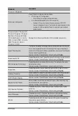
COM1 Console Redirection
Settings (continued)
Parity
– A parity bit can be sent with the data bits to detect some
transmission errors.
– Even: parity bit is 0 if the num of 1's in the data bits is even.
– Odd: parity bit is 0 if num of 1's in the data bits is odd.
– Mark: parity bit is always 1. Space: Parity bit is always 0.
– Mark and Space Parity do not allow for error detection.
– Options available: None, Even, Odd, Mark, Space. Default setting
is
None
.
Stop Bits
– Stop bits indicate the end of a serial data packet. (A start bit
indicates the beginning). The standard setting is 1 stop bit.
Communication with slow devices may require more than 1 stop
bit.
– Options available: 1/2. Default setting is
1
.
Flow Control
–
Flow control can prevent data loss from buffer overflow. When
sending data, if the receiving buffers are full, a 'stop' signal can
be sent to stop the data flow. Once the buffers are empty, a 'start'
signal can be sent to re-start the flow. Hardware flow control uses
two wires to send start/stop signals.
– Options available: None, Hardware RTS/CTS. Default setting is
None
.
VT-UTF8 Combo Key Support
– Enable/Disable the VT-UTF8 Combo Key Support.
– Options available: Enabled/Disabled. Default setting is
Enabled
.
Recorder Mode
(Note)
– When this mode enabled, only texts will be send. This is to capture
Terminal data.
– Options available: Enabled/Disabled. Default setting is
Disabled
.
Resolution 100x31
(Note)
– Enable/Disable extended terminal resolution.
– Options available: Enabled/Disabled. Default setting is
Enabled
.
Putty KeyPad
(Note)
– Selects FunctionKey and LeyPad on Putty.
– Options available: VT100, LINUX, XTERMR6, SC0, ESCN, VT400.
Default setting is
VT100
.
Summary of Contents for H261-NO0
Page 1: ...H261 NO0 H261 PC0 HCI Server Intel DP 2U 4 Nodes Server User Manual Rev 1 0 ...
Page 10: ...This page intentionally left blank ...
Page 33: ...System Hardware Installation 33 1 2 3 4 1 4 3 2 ...
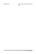
Page 47: ... 47 System Hardware Installation LAN Bridge Cable On Board SATA to HDD Back Plane Board Cable ...
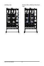
Page 50: ...System Hardware Installation 50 LAN Bridge Cable On Board SATA to HDD Back Plane Board Cable ...
Page 74: ...BIOS Setup 74 5 3 1 Processor Configuration ...


