background image

5

Introduction

Your telephone company may make changes in its facilities, equipment, operations, or procedures that
could affect proper operation of your equipment. If they do, you will be notified in advance to give you an
opportunity to maintain uninterrupted telephone service.
The FCC prohibits this equipment to be connected to party lines or coin-telephone service.
The FCC also requires the transmitter of a FAX transmission be properly identified (per FCC Rules Part
68, Sec. 68.381 (c) (3)).
/ for Canadian users only /

L

Canadian Department of Communications Compliance Statement

This digital apparatus does not exceed the Class B limits for radio noise emissions from digital

apparatus as set out in the radio interference regulations of Industry Canada.
Le present appareil numerique n'emet pas de bruits radioelectriques depassant les limites applicables aux
appareils numeriques de Classe B prescrites dans le reglement sur le brouillage radioelectrique edicte par
Industrie Canada.

L

DOC notice (for products fitted with an Industry Canada-compliant modem)

The Canadian Department of Communications label identifies certified equipment. This certification

means that the equipment meets certain telecommunications network protective, operational and safety
requirements. The Department does not guarantee the equipment will operate to the user satisfaction.
Before installing this equipment, users ensure that it is permissible to be connected to the facilities of the
local Telecommunications Company. The equipment must also be installed using an acceptable method
of connection. The customer should be aware that compliance with the above conditions might not prevent
degradation of service in some situations.
Repairs to certified equipment should be made by an authorized Canadian maintenance facility designated
by the supplier. Any repairs or alterations made by the user to this equipment, or equipment malfunctions,
may give the telecommunications company cause to request the user to disconnect the equipment.
Users should ensure for their own protection that the electrical ground connections of the power utility,
telephone lines and internal metallic water pipe system, if resent are connected together. This precaution
may be particularly important in rural areas.
Caution: Users should not  attempt to make such connections themselv es, but should contact the
appropriate electric inspection authority, or electrician, as appropriate.

Summary of Contents for GS-SR326

Page 1: ...System Installation Guide GS SR326 Rack Mount Tower Dual XeonTM Processor Motherboard Server Solution Rev 1001 22ME2 SR326 00 ...

Page 2: ... Step 2 2 CPU Installation 10 Step 2 3 Heat Sink Installation 11 Step 2 4 Memory Installation 12 Step 2 5 PCI Expansion Card Installation 12 Step 2 6 Hard Disk Drive Installation 13 Step 2 7 Reinstall Top Cover 14 Step 2 8 Accessory Kits Installation 14 Chapter 3 Appearance of GS SR326 18 3 1 Front View of GS SR326 18 3 2 Rear View of GS SR326 18 3 3 Switch and LED Indicators Description 19 Chapte...

Page 3: ...ct usage instructions Do not use this product near water or a heat source Set up the product on a stable work surface or so as to ensure stability of the system Openings in thecaseare provided forventilation Do notblock or coverthese openings Makesure you provide adequatespace around thesystem for ventilationwhen you set upyour work area Never insert objects of any kind into the ventilation openin...

Page 4: ...e at his own expense Properly shielded and grounded cables and connectors must be used in order to meet FCC emission limits Neither the provider nor the manufacturer are responsible for any radio or television interference caused by using other than recommended cables and connectors or by unauthorized changes or modifications to this equipment Unauthorized changes or modifications could voidthe us...

Page 5: ...certified equipment This certification means that the equipment meets certain telecommunications network protective operational and safety requirements The Department does not guarantee the equipment will operate to the user satisfaction Before installing this equipment users ensure that it is permissible to be connected to the facilities of the local Telecommunications Company The equipment must ...

Page 6: ...rcentage of the total load to be connected to a telephone loop which is used by the device to prevent overloading The termination on a loop may consist of any combination of devices subject only to the requirement that the sum of the Load Numbers of all the devices does not exceed 100 for European users only ...

Page 7: ...ff before you plug in or remove theATX power connector on the motherboard WARNING þ Chassis þ Power Supply Installed þ The GA 8EGXDR motherboard þ Silm ype CD ROM drive Installed þ Silm type Floppy drive Installed þ Six Hadr Disk Drive Trays þ Two CPU Heat Sinks þ Driver CD for motherboard driver utility þ GA 8EGXDR user s manual þ SR326 System Installation Guide þ Accessory Kits Item Checklist In...

Page 8: ...in DDR DIMM sockets Supports 4 ECC Register DIMM DDR200 Supports up to 4 GB DRAM Max Network Interface Build in Intel 82550PM 10 100 Fast Ethernet Intelligent Management Support IPMI V1 0 Optioal RAID Supported Support LSI software IDE RAID 0 1 5 Optional Mass Storage System 6 Hot Swappable SCSI HDD One slim type flexible FDD Drive One silm type CD ROM drive I O Expansion Slots PCI X 100MHz x 2 sl...

Page 9: ...Floppy port up to 2 88MB One Parallelport EPP ECP Two Serial ports 4 USB ports Version 1 1 One RJ45 LAN ports PS 2 Keyboard and Mouse connectors BIOS LicensedAward BIOS 4Mb flash ROM Power Supply Maximum 350W redundant Power Supply supported ...

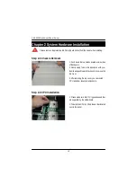
Page 10: ...lation 1 Push down the twobuttons located at two sides of the chassis 2 Gently apply force to the indentures with your thumbs andpush toward the chassis to remove the top cover 3 After removing the top cover you can install CPU and other essential components 1 Please makesure the CPU typeand speed that are supported by the motherboard 2 To install the CPU s lift up the bar that located next to the...

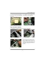
Page 11: ...cketto the CPU Make sure middlepart of bracket is clicked into the desired position Then hook the other end of the cooler bracketby gripping itto anothersideof reten tion module 3 Thenoticed corner shouldpoint toward theend of lev er The CPU will only it in the orientation as shown below 4 Then alignthe CPU and insert itinto the socket Then push the lever to the original position ...

Page 12: ...heDIMM memory module only fit in one direction 2 Align the memory notch to the module and push the memory into the DIMM socket 1 Remove the screw on the top of the bracket 2 Push the expansion card firmly into expansion slot in motherboard 3 Replace the screw to secure the slot bracket of the expansion card 4 Installation is completed ...

Page 13: ...e hard disk tray 2 Pull out the Hard Disk try 3 Hard Disk Tray 1 Uncrew thethumbscrew from the frontof server 5 Secure hard disk in the hard disk tray with screws Forsecurity reason you should tighten all screws into the pointed position 6 Relacehard disk tray intothe server Installation completed ...

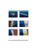
Page 14: ...ly apply force to the indentures with your thumbs andpush toward the chassis to replace the top cover 1 Accessory kits introduction Step 2 8 Accessory Kits Installation Rear view of bezel welding LED Front view of bezel welding LED Foot stand plates Hinge cover asscessory ...

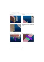
Page 15: ...15 Hardware Installation Process Lock bracket Top plastic cover 2 Remove CR R door 3 Secure lock bracket with screw 5 Reinstall CR R door 4 Make sure lock bracket is firmly screwed ...

Page 16: ...rection shownin the pictureto install the front bezel 8 Then push the other side of bezel LED into the system 7 Gripping the hook into the system as the cip circle pointed 9 Secure foot stand plate with screws 10 Foot stand plate installation completed ...

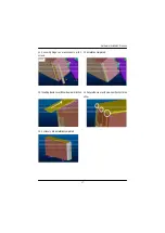
Page 17: ...ocess 11 Assembly hinge cover acccseeory w ith 2 screws 12 Installation completed 13 Insert topplastic coverfollow thearrow direction 14 Secure thecover with srews as theclip circles show 15 Accessory kits installation completed ...

Page 18: ...View of GS SR326 Chapter 3 Appearance of GS SR326 Six Hot swappable SCSI HDD Slim type CD ROM optional Slim type FDD 2 x 5 25 bayspace PS 2 connectors USB connectors COM port Parallel port VGA port LAN ports 7 PCI full height Add on cards System Cooling FAN Redundant Power ...

Page 19: ...witch Push Gently N A Reseting Buzzer Stop Switch Push Gently N A Buzzer stop Power LED On Off Green N A System power on System power off HDD Access LED Blink Off Green N A HDD accessing HDD idle ERROR LED On Off Amber N A System error occurs System status normal HDD Access LED Error LED Sleep Switch Power LED Buzzer Stop Switch Reset Switch ...

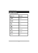
Page 20: ...20 GS SR326 Rack mount Tower Server Chapter 4 Appendix 4 1 Connector Icon Description Suggest Icon Description Keyboard VGA Mouse LAN Parallel Port Serial Port USB ...

Reviews: