background image

GS-SR125E System Installation Guide 

15 


5.6. 

PCI Expansion Card Installation 

GS-SR125 provides expansion riser slots for two peripheral cards, 

64Bit/66 MHz full-height. To install the peripheral, please go 

through the following steps. 

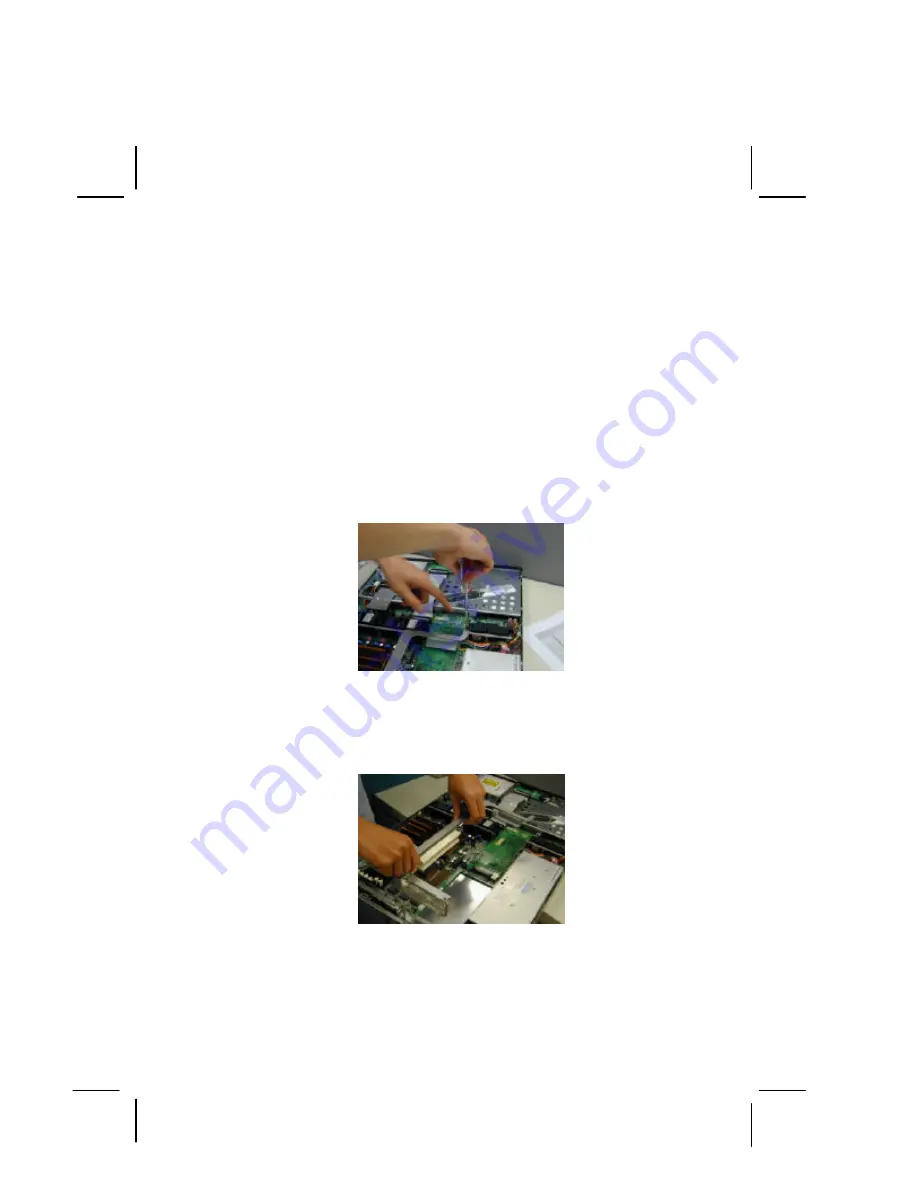
Step 1.

 There are screws holding the riser bracket. Remove the 

screw on the top of the bracket.  


Figure 12 

Step 2. 

Pull the bracket straight up. (Fig-13) 


Figure 13 

Summary of Contents for GS-SR 125E

Page 1: ...GS SR 125E Rack Mount Server System Installation Guide ...

Page 2: ......

Page 3: ...CPU INSTALLATION 12 5 4 HEAT SINK INSTALLATION 13 5 5 MEMORY INSTALLATION 14 5 6 PCI EXPANSION CARD INSTALLATION 15 5 7 REINSTALL TOP COVER 17 5 8 SCSI ID SETTING FOR SCSI MODEL ONLY 18 5 9 HARD DISK DRIVE INSTALLATION 20 5 10 MOTHERBOARD LAYOUT JUMPER SETTING 22 5 11 APPEARANCE OF GS SR125E 24 5 11 1 FRONT VIEW OF GS SR125E 24 5 11 2 REAR VIEW OF GS SR125E 24 5 11 3 LED INDICATOR DESCRIPTION 25 5...

Page 4: ...he information contained herein Third party brands and names are the property of their respective owners Third party brands and names are the property of their respective owners Please do not remove any labels on server system this may void the warranty of this server Due to rapid change in technology some of the specifications might be out of date before publication of this booklet ...

Page 5: ... electrical grounding type plug only fits into a grounding type power outlet This is a safety feature The equipment grounding should be in accordance with local and national electrical codes The equipment operates safely when it is used in accordance with its marked electrical ratings and product usage instructions n Do not use this product near water or a heat source n Set up the product on a sta...

Page 6: ...shock from lightning n To reduce the risk of fire use only No 26 AWG or larger telecommunications line cord n Do not plug a modem or telephone cable into the network interface controller NIC receptacle n Disconnect the modem cable before opening a product enclosure touching or installing internal components or touching an uninsulated modem cable or jack n Do not use a telephone line to report a ga...

Page 7: ... not cause harmful interference and 2 this device must accept any interference received including interference that may cause undesired operation FCC part 68 applicable to products fitted with USA modems The modem complies with Part 68 of the FCC Rules On this equipment is a label that contains among other information the FCC registration number and Ringer Equivalence Number REN for this equipment...

Page 8: ... certification means that the equipment meets certain telecommunications network protective operational and safety requirements The Department does not guarantee the equipment will operate to the user satisfaction Before installing this equipment users ensure that it is permissible to be connected to the facilities of the local Telecommunications Company The equipment must also be installed using ...

Page 9: ...ppropriate electric inspection authority or electrician as appropriate NOTICE The Load Number LN assigned to each terminal device denotes the percentage of the total load to be connected to a telephone loop which is used by the device to prevent overloading The termination on a loop may consist of any combination of devices subject only to the requirement that the sum of the Load Numbers of all th...

Page 10: ...etain for future reference The procedures in this guidebook assume that you are a system or network administrator experienced in installing similar hardware The user s guide is organized as follows Chapter 3 Introduction provides the basic product information and the key features of the product Chapter 4 Contents Package lists the essential hardware installation components Chapter 5 System Install...

Page 11: ...owing tips l Go through the installation guide carefully before starting the system installation processes l Keep the system away from static and magnetic field l Do not apply any cleaning solutions directly to the system 3 1 Feature of SCSI Model The Gigabyte GS SR125E is a rack optimized server that offers superior performance and scalability to your networking system It contains the several fea...

Page 12: ...ROM bootable l AC recovery ON OFF control l Auto detect report system health status Chipset l Intel E7501 Chipset l Intel MCH ICH3 and P64H2 Memory Supported l Support DDR memory up to 12GB l DIMM socket x 6 l 2 Channels 266Mhz DDR 3 REG DIMM Channel Integrated SCSI Controller l Adaptec 7902W U320 Dual Channel SCSI Controller Compliance design upgraded to 7902 U320 l Zero Channel RAID Integrated I...

Page 13: ...wappable drives l One standard FDD drive Optional device l One slim type CD ROM drive System Form Factor l 1U Rack optimized design I O expansion slots l 2 raisers cards to support 3 PCI expansion l First Raiser Card with 2 slots Support PCI X full height full length 100MHz Support PCI X full height half length 100MHz l Second Raiser Card with 1 slot Support PCI low profile 64 Bit 66MHz ZCR Power ...

Page 14: ...rify the contents If any component is missing or damaged in the system please contact your vendor immediately 4 1 Component Content List For SCSI Model l Chassis l Power Supply Installed l 8IPP533 Motherboard Installed l Slim type CD ROM drive Installed l Four Hard Disk Drive Trays l Two CPU heat sinks l Two thumbscrews l Driver and Application CD l GS SR125E System Installation Guidebook ...

Page 15: ...stem when installing 5 2 Chassis Removal Step 1 Push down the two buttons located at two sides of the chassis Fig 1 Figure 1 Figure 2 Step 2 Gently apply force to the indentures with your thumbs and push toward the chassis to remove the top cover Fig 2 Step 3 After removing the top cover you can install CPU and other essential components ...

Page 16: ...re the CPU type and speed that are supported by the motherboard Step 2 To Install the CPU s lift up the bar that located next to the socket Fig 3 Figure 3 Step 3 The noticed corner should point toward the end of lever The CPU will only fit in the orientation as shown Fig 4 Figure 4 ...

Page 17: ...g 5 Push the lever back to the original position Fig 6 Figure 5 Figure 6 5 4 Heat Sink Installation Step 1 Put the Heat sink on the CPU Fig 7 Figure 7 Figure 8 Step 2 There are for screws hold the retention modules Seat the heat sink firmly in the retention modules with the two cooler brackets ...

Page 18: ...sition Fig 8 Step 5 Hook the other end of the cooler bracket by gripping it to another side of retention module Fig 9 Figure 9 5 5 Memory Installation The motherboard contains six DIMM Dual Inline Memory Module sockets The systems BIOS will auto detect the size if the memory after installing To install memory simply push the memory modules into the DIMM sockets Fig 10 11 Figure 10 Figure 11 ...

Page 19: ...s expansion riser slots for two peripheral cards 64Bit 66 MHz full height To install the peripheral please go through the following steps Step 1 There are screws holding the riser bracket Remove the screw on the top of the bracket Figure 12 Step 2 Pull the bracket straight up Fig 13 Figure 13 ...

Page 20: ...module Fig 14 Figure 14 Figure 15 Step 3 Secure the card with screws Fig 15 Step 4 Repeat Step 2 to install another card Fig 16 Step 5 Secure the card with screws Fig 17 Figure 16 Figure 17 Step 6 Finally align the stable racks to the system module see the arrow direction and push down vertically to complete the installation Fig 18 ...

Page 21: ...e installation of the entire essential components from subsection 5 1 to 5 7 replace the plastic air duct This will secure the airflow is inside the chassis Failure to do so may cause CPU and Memory over heating Replace top cover insuring that the thumbscrews are tightened Fig 19 Figure 19 ...

Page 22: ... 8 SCSI ID Setting For SCSI Model ONLY The SCSI ID is shown in Figure 20 If there occurs an abnormal SCSI hard disk drive behavior e g does not detect the hard disk drive properly please make sure that the each HDD has different ID Figure 20 ...

Page 23: ... ON ON ON ON 1 ON ON ON OFF 2 ON ON OFF ON 3 ON ON OFF OFF 4 ON OFF ON ON 5 ON OFF ON OFF 6 ON OFF OFF ON 7 ON OFF OFF OFF 8 OFF ON ON ON 9 OFF ON ON OFF A OFF ON OFF ON B OFF ON OFF OFF C OFF OFF ON ON D OFF OFF ON OFF E OFF OFF OFF ON F OFF OFF OFF OFF ON Jumper Close 1 2 OFF Jumper Open 2 3 ...

Page 24: ...is Fig 21 Insert the hard disk drive into the tray Secure each hard disk drive with screws Fig 22 to 24 Figure 21 Figure 22 Figure 23 Figure 24 Step 2 After securing the hard disk drive with the screws hold the hard drive handle at open position place the tray into chassis Fig 25 and push the hard disk drive tray handle to the closed position Fig 26 ...

Page 25: ...GS SR125E System Installation Guide 21 Figure 25 Figure 26 ...

Page 26: ...GS SR125E System Installation Guide 22 5 10 Motherboard Layout Jumper Setting D C B A Health LED ID LED Switch E ...

Page 27: ...tion 1 1 2 Close Clear CMOS 1 2 3 Close Normal Default Value 1 1 2 Close VGA Enabled Default Value 1 2 3 Close Onboard VGA Disabled 1 2 Close BIOS Top Block Write Protect 1 2 3 Close BIOS 2 8 Block Write Protect 1 1 2 Close Disable USB device Wake up Function Default Value 1 2 3 Close Enable USB device Wake up Function 1 1 2 Close Disable USB device Wake up Function Default Value 2 3 Close Enable ...

Page 28: ... 11 1 Front View of GS SR125E 5 11 2 Rear View of GS SR125E SCSI Ultra 160 Hot Swap HDD USB LED Manufacture Option Floppy Disk 4th HDD tray PS 2 Keyboard and Mouse connectors USB connectors COM Port VGA Port LAN1 2 Ports Half Length Full Height Full Length ID LED Button ...

Page 29: ...GS SR125 Series System Installation Guide 25 5 11 3 LED Indicator Description Acting Color Status On Green Power On On Amber Power cable plug in Blink Green System stands by Power LED Off N A No power ...

Page 30: ...ber Critical Power Modules Failure Critical FANs Failure Voltage Power Supply Critical Temperature and Voltage SYS LED Off N A Non critical temperature and voltage On Green LAN online Off N A LAN offline LAN LED Blinking Green LAN acting On Blue Identified by service people ID SERVICE LED Off N A N A ...

Page 31: ...HDD LED Acting Color Status HDD LED 1 Off N A HDD Idle HDD LED 1 Blink Green HDD Acting HDD LED 2 Off N A No error HDD LED 2 On Green Faulty or rebuild stop HDD LED 2 Slow Blink Green Rebuild HDD LED 2 Fast Blink Green Identify HDD LED 1 HDD LED 2 ...

Page 32: ...over Fig 28 Push down the two buttons located at two sides of the system to remove front top cover Follow the arrow direction shown in Fig 29 Figure 27 Figure 28 Step 2 Insert the floppy disk drive into the tray Secure the floppy disk drive with screws Fig 30 Connect cables to the floppy disk drive Fig 31 Figure 29 Figure 30 ...

Page 33: ...ray into chassis Fig 32 and push the floppy disk drive tray handle to the closed position Note It will make click sound when the floppy disk drive is inserted properly Figure 31 Figure 32 Step 4 Connect the floppy drive disk to the necessary cables and power Fig 33 ...

Page 34: ...GS SR125E System Installation Guide 30 5 13 Connector Icon Description Suggested icons Description Keyboard VGA Mouse LAN Parallel Port Serial Port USB ...

Reviews: