background image

1 4

GS-R1161-RH Rack Mount Server

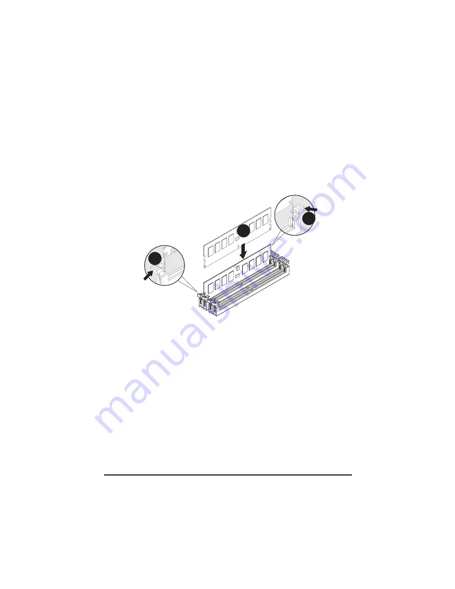
Step 2-4: Memory Installation

Step 1. Insert the DIMM memory module vertically into the DIMM slot, and push it  down.
Step 2. Close the plastic clip at both edges of the DIMM slots to lock the DIMM module.
NOTE! DIMM must be populated in order starting from DIMM6 socket. For dual-channel
operation, DIMMs must be installed in matched pairs.
Step 3. Reverse the installation steps when you wish to remove the DIMM module.

2

2

1

Summary of Contents for GS-R1161-RH

Page 1: ...System Installation Guide GS R1161 RH 1U Rack Mount Server Intel Xeon LGA775 Processor Serverboard Rev 1 0 ...

Page 2: ...are Installation 11 Step 2 1 Chassis Removal and Installation 11 Step 2 2 CPU Installation 12 Step 2 3 Heat Sink Installation 13 Step 2 4 Memory Installation 14 Step 2 5 PCI Expansion Card Installation 15 Step 2 6 Hard Disk Drive Installation 16 Step 2 7 FAN Duct Removal and Installation 17 Chapter 4 Motherboard Jumper Setting 18 4 1 GA 5YXS2 RH Motherboard Jumpper Setting 18 ...

Page 3: ...3 Table of Content ...

Page 4: ...usageinstructions Do not use this product near water or a heat source Set up the product on a stable work surface or so as to ensure stability of the system Openingsinthecaseareprovidedforventilation Donotblockorcovertheseopenings Makesureyou provide adequate space around the system for ventilation when you set up your work area Never insert objects of any kind into the ventilation openings To avo...

Page 5: ...is own expense Properly shielded and grounded cables and connectors must be used in order to meet FCC emission limits Neither the provider nor the manufacturer are responsible for any radio or television interference caused by using other than recommended cables and connectors or by unauthorized changes or modificationstothisequipment Unauthorizedchangesormodificationscouldvoidtheuser sauthorityto...

Page 6: ...rtmentofCommunicationslabelidentifiescertifiedequipment Thiscertification meansthattheequipmentmeetscertaintelecommunicationsnetworkprotective operationalandsafety requirements TheDepartmentdoesnotguaranteetheequipmentwilloperatetotheusersatisfaction Beforeinstallingthisequipment usersensurethatitispermissibletobeconnectedtothefacilitiesofthe localTelecommunicationsCompany Theequipmentmustalsobein...

Page 7: ...ading The termination on a loop may consist of any combination of devices subject only to the requirement that the sum of the Load Numbers of all the devices does not exceed 100 for European users only CAUTION Danger of explosion if battery is incorrectly replaced Replace only with the same or equivalent typerecommendedbythemanufacturer Disposeofusedbatteriesaccordingtothe manufacturer sinstructio...

Page 8: ...talling all the essential components for the sever system Foryourprotection pleasereadandundertandallofthesafetyandoperatinginstructionsregardingyour Gigabyte Server and retain for future reference The procedures in this guidebook assume that your are a system or network administrator experienced in installing similar hardware Contents Packages Whenopeningthepackage pleaseensure thesystemcomponent...

Page 9: ...y 1 Riser card supports 1 PCI E x8 and 1 PCI E x8 x1 bandwidth add oncards y 1 SO DIMM add on card SATA RAID controller y ICH9R y Supports LSI Software SW RAID 0 1 10 Windows only Cooling Fans y 5 X System Fan Integrated LANs Controller y Intel 82566DC 82573VGbE controllers Integrated Graphics Controller y XGI Volari Z9s Graphics Memory y 32MB DDR2 Mass Storage System y 4 x Hot Swap SATA HDDs Supe...

Page 10: ...y 32KB Nonvolatile Memory to Log System Failure Events RemoteManagement y Follow the IPMI 2 0 specification of Server management Environment AmbientTemperature y OperatingTemperature 5o C to 40o C y Non operatingTemperature 0o C to 50o C Relative Humidity y 10 80 operating Humidity at 30o C System Dimention y 427 5mm x 567 5mm x 43 5 mm Electrical Power Supply y Single Power Supply 300W ...

Page 11: ...ental conditions Protect it from dust humidity and heat Step 2 1 Chassis Removal and Installation Step 1 Push down the indentation located at two sides of the chassis Step 2 Slide toward the top chassis cover Step 3 Lift up to remove the top chassis cover Step 4 Reverse Step 1 2 3 to replace the chassis cover Chapter 2 System Hardware Installation 1 3 2 1 ...

Page 12: ... make sure the CPU type and speed that are supported by the motherboard Step1 Raise the metal locking lever on the socket Insert the CPU with the correct orientation Step2 The CPU only fits in one orientation Step3 Push the metal lever back into locked position 1 2 3 ...

Page 13: ...tion Step 1 Place the Heat Sink on the CPU Before putting the heat sink on the CPU please well remember to apply the thermal conductivity compound on the CPU Step 2 Seat the heat sink in the retention modules with the four screws Installation completed 1 2 2 2 2 ...

Page 14: ... slot and push it down Step 2 Close the plastic clip at both edges of the DIMM slots to lock the DIMM module NOTE DIMM must be populated in order starting from DIMM6 socket For dual channel operation DIMMs must be installed in matched pairs Step 3 Reverse the installation steps when you wish to remove the DIMM module 2 2 1 ...

Page 15: ...lling the expansion card please check the card size limitation Size limitation for standard riser card is 182mm and the size limitation for low profile riser card is 182mm Step 1 Loosen the riser bracket screws Step 2 Lift the riser bracket slightly then pull it out from the server chassis Step 3 Aligntheexpansioncardwiththeguidinggroove Slidetheexpansioncardintotheslotuntilthe card firmly seats S...

Page 16: ...Drive Installation Step 1 Pressthereleasebutton Step 2 Pull the blank out of the drive bay Step 3 Slide hard disk into blank Step 4 Secure it with screws Step 5 Slide the blank into the bay until it locks into place Connect cable and power 1 2 3 4 4 4 4 ...

Page 17: ...17 Hardware Installation Process Guiding groove Step 2 7 FAN Duct Removal and Installation Step 1 Align the fan duct with the guiding groove Push down the fan duct into system ntil the its firmly seats ...

Page 18: ...18 MotherboardLayout 4 1 GA 5YXS2 RH Motherboard Jumpper Setting Chapter 4 Motherboard Jumper Setting CLR_CMOS1 RECOVERY1 ...

Page 19: ...his jumper Default value doesn t include the Shunter to prevent from improper use this jumper To clear CMOS temporarily short 1 2 pin 2 RECOVERY1 BIOS Revocery jumper 1 2 Close Normal operation Default setting 2 3 Close Clear CMOS 1 1 1 1 1 2 Close Enable BIOS Recovery function 2 3Close Normaloperation Defaultsetting ...

Reviews: